
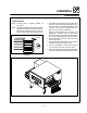
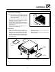
Specifications

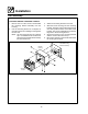

Installation
15
Oven Assembly
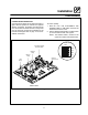
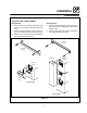
CONVEYOR BELT TENSIONER
NOTE: Each tensioner installs between the idle
end of the conveyor (the side opposite the
drive) and the bracket under each con-
veyor support angle.
1. The belt tensioner contains a spring t o adjust
the length. Compress the spring to shorten
the length of the belt tensioner.
2. Insert the pin on the end of the tensioner into
the hole in the bracket under each conveyor
support angle.
3. Expand the tensioner to engage the pin lo-
cated on the conveyor ra ck.
Belt
Tensioner
Figure 12
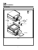
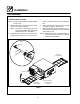
CRUMB PANS
1. Slidethedrivesidecrumbpanunderthecon-
veyor rack from the front. The notch in the
crumb pan must line up with the drive shaft.
2. When the notch is lined up with the drive shaft,
push the crumb pan into the coo king chamber.
Hook the end of the crumb pan over the end of
theconveyorrack.
3. Slide the idle side crumb pan under the end of
theconveyorrack.
4. Slide the product stop over the end of the idle
side crumb pan.
Drive Side
Crumb Pan
Idle Side
Crumb Pan
Product
Stop
Figure 13