
User's Manual


ENG man MITO-VETTA 915 00 Radio Remote Control System MITO-VETTA-915
- Page 5 -
ENGLISH
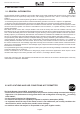
2.5 RECEIVING UNIT AR MITO-MINI-915
PRESSACAVO
M20
MODULO RADIO
SCHEDA BASE
MORSETTIERA
SPIA POWER
SPIA STATUS
SPIA LEARN
DIP SWITCH
MODULO RADIO
DIP SWITCH
SCHEDA BASE
CONNETTORE
ANTENNA
ESTERNA
SPIA CHECK
MODULO RADIO
FUSIBILE SU
RELE' T1
OPZIONE
PRESSACAVO
M16
GENERAL FEATURES.
• Self-diagnosis.
The system runs a diagnostic test (CHECK light blinks twice per second) during the rst ve seconds after receiver
power-on.
CHECK light blinks once every 2 seconds SYSTEM OK.
CHECK light on steady SYSTEM FAILURE.
• Output commands.
Relay T1 (Stop) is active when the radio connection between transmitter and receiver is active. Relay T1 (Stop) is
protected by fuse F1 (6.3A).
Relay T12 (Alarm) is activated at the press of T8 (Alarm) on the transmitter.
• Indicator lights.
POWER LIGHT indicates the system is powered on.
STATUS LIGHT blinks once per second to indicate that radio connection is active.
LEARN LIGHT provides indications when in programming mode.
• External antenna option.
Bring the external antenna cable to cable gland M16 which you will have prepared previously. Connect the external
antenna to the connector on the radio module; do not force the connection. Tighten the cable gland on the largest
diameter cable only.
• Terminal block and wiring.
Maximum useful cross-section area 2.5 sq mm. For wiring connections, follow the mother board layout and the wiring
examples provided in ANNEX and annexed documents.
LEARN LIGHT
STATUS LIGHT
POWER LIGHT
DIP SWITCH
RADIO MUDULE
DIP SWITCH
MOTHER BOARD
MOTHER BOARD
M16
CABLE GLAND
OPTION
M20
CABLE GLAND
OPTION
FUSE ON
RELAY T1
RADIO MODULE
CHECK LIGHT
TERMINAL BLOCK
EXTERNAL
ANTENNA
CONNECTOR
RADIO MODULE