R600 Operation and Installation manual for authorized technicians only Betriebsanleitung für die autorisierte Fachkraft Bedienings- en Installatiehandleiding alleen voor bevoegde vakmensen Notice d’installation et d’emploi réservée à l’usage des techniciens agréés Istruzioni per l'uso solo per il tecnico autorizzato 07/2010 DOC3070 / 12099579
Operation and Installation manual for authorized technicians only R 600 07/2010 DOC3070 / 12099579
Contents 2 Contents .................................................................. 2 Safety General regulations ................................... Application ................................................. Norms and regulations .............................. 3 3 3 Construction Layout of boiler .......................................... Operating principle .................................... 4 4 Technical data ..................................................................
Safety General regulations Application Norms and regulations General regulations This documentation contains important information, which is a base for safe and reliable installation, commissioning and operation of the R600 boiler. All activities described in this document may only be excecuted by authorized companies. Changes to this document may be effected without prior notice. We accept no obligation to adapt previously delivered products to incorporate such changes.
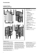
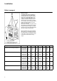
Construction Layout of boiler Operating principle 1 5 4 2 7 6 Layout of boiler The R600 boiler consists of the following main components: 1 2 3 4 5 6 7 8 9 10 11 12 13 14 3 8 14 13 24 22 15 Operating principle The R600 is a fully modulating boiler. The control unit of the boiler adapts the modulation ratio automatically to the heat demand requested by the system. This is done by controlling the speed of the fan.
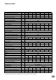
Technical data R601 R602 R603 R604 R605 R606 R607 Nominal heat output at 80-60ºC max/min* kW 142.1/23.3 190.1/39.5 237.2/39.5 285.2/39.5 380.2/76.6 475.3/76.6 539.0/76.6 Nominal heat output at 75-60ºC max/min* kW 142.2/23.5 190.3/39.5 237.4/39.5 285.5/39.5 380.6/76.6 475.8/76.6 539.6/76.6 Nominal heat output at 40/30ºC max/min* kW 150.7/26.7 201.6/45.2 251.4/45.1 302.3/45.2 403.1/87.7 503.9/87.7 571.5/87.7 Nominal heat input Hi max/min* kW 145.0/24.5 194.0/41.5 242.0/41.5 291.0/41.5 388.
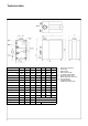
Technical data Dimension R601 R602 R603 R604 R605 R606 R607 L mm 1105 1260 1470 1220 1435 1585 1735 L2 mm 127.5 127.5 137.5 137.5 187.5 187.5 187.5 H mm 1480 1480 1500 1500 1500 1500 1500 H2 mm 1120 1130 1130 1150 1245 1245 1245 B mm 670 670 670 770 770 770 770 B2 mm 225 235 235 235 215 215 215 B3 mm 260 260 260 310 310 310 310 B4 mm 260 260 260 490 490 490 490 B5 mm 130 130 130 245 245 245 245 D1 mm (Diam.
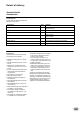
Extent of delivery Standard boiler Accessories Standard boiler A boiler delivery package contains the following components: Component Pcs. Package Boiler fully assembled and tested 1 Adjustable feet 4 Syphon for condensate connection 1 Conversion kit for natural gas L and propane incl.
Installation Boiler transport 1 2 Boiler transport The R600 boiler will be supplied as a complete unit being fully assembled and pre-tested. The maximum width is 670mm for models R601-R603 and 770mm for models R604-R607, which makes it possible to transport all models through a normal door in one piece. The boiler can be transported with a pallet truck, entering either from the front or from the side.
Installation Removing the casing Boiler transport Remove the casing before transporting the boiler, in order to avoid damage to the casing parts during transportation. Removing the casing is done as follows: 1. 4. 2. 3. 6. 5.
Installation Boiler installation Boiler installation The boiler should be positioned in a frost-proof boiler room. If the boiler room is on the roof, the boiler itself may never be the highest point of the installation. When positioning the boiler, please note the recommended minimum clearance in the picture. When the boiler is positioned with less free space, maintenance activities will be more difficult.
Installation Connecting the boiler 1 3 Connecting the boiler This chapter will explain how to make all connections to the boiler with regard to: Hydraulic connections Condensate drain connection Gas connection Flue gas connection Air intake connection (under casing) Electrical connection The boiler should always be connected in such a way, that the system applies to all relevant standards and regulations (European, national and local).
Installation Connecting the boiler 1 7 3 Gas connection (1) The gas connection must be made by an authorized installer in accordance with the applicable national and local standards and regulations. Connect the gas line from the system tension free to the gas connection (1) of the boiler. A gas cock should be mounted directly behind the boiler. A gas filter can be mounted directly on the gas connection of the boiler.
Commissioning Water and hydraulic system Commissioning of the boiler should be carried out by authorized personnel only. Failure to respect this condition makes the guarantee void. A protocol of the commissioning should be filled out (see end of this chapter for example of commissioning protocol). This chapter explains the commissioning of the boiler with the standard boiler controller. When an additional system controller is installed, please refer to its manual for commissioning the controller.
Commissioning Gas supply Condensate connection Flue and air intake connections 1 Gas supply Check the gas supply connection to the boiler for tightness. If any leakage is found, reseal the leakage before starting the boiler! Remove any air between the gas valve and the gas line. This can be done at the test point (1) at the gas pressure switch.
Commissioning Prepare boiler for first startup Legend: A On/off switch B Return (ESC) C Room temperature control D Confirmation (OK) E Manual mode F Chimney sweeper mode G Info mode H Reset button I Operation mode heating zone(s) L Display M Operation mode DHW 1 I M L G A H B C D E F Preparation for first startup Open the gas supply; Enable the power supply to the boiler; Switch on the boiler with the on/off switch (1); Make sure the boiler is in standby mode (K); Check the pump opera
Commissioning Combustion analysis Combustion check at full load Start the boiler in controller stop mode and go to full load operation (100%). Now the boiler operates at 50% load. Allow the boiler to stabilise the combustion for 3 minutes. Then increase the boiler load step by step up to 100%. Check the gas pressure on the inlet of the gas valve while increasing the boiler load: the gas pressure should never go below the minimum required value see technical data.
Commissioning Check water flow Check water flow The water flow through the boiler can be checked with two different methods shown below. ∆T measurement Check the temperature difference over the boiler (∆T flow-return) when the boiler is running on 100% load. The nominal ∆T is 20K and must be at least between 15K and 25K for secure boiler operation.
Commissioning Check functionality of safety devices Gas tightness check Boiler shut down 1 2 3 5 4 Check functionality of safety devices All safety devices have to be checked on good functioning. Safety devices on a standard boiler are a water flow temperature sensor, fluegas temperature sensor, water flow switch minumum gas pressure switch and ionisation electrode. These devices can be checked as described below.
Commissioning Commissioning protocol Commissioning Protocol R600 Project Boiler type Project Serial number Address Year City Nominal load (Hi) [kW] Date Nominal output (Hi) [kW] Engineer [bar] Installation: System Water pressure Water pH [-] Water hardness [dºH] Water chloride [mg/l] Water ∆T full load [ºC] [kPa] Water ∆pboiler [m3/h] Water flow Pump setting [-] Hydraulics: Roof top Ground floor Basement Other: .........................
Operating instructions Controls I M L G A H B C D E F Operation mode DHW (M) For switching on the DHW operation (indication in display below DHW symbol) Confirmation (OK) (D) Return (ESC) (B) These buttons are used for programming in combination with the wheel.
Operating instructions Display / Programming DHW mode selection Heating operation mode selection (Controller Stopp mode when pressing > 3 sec.) Display Info button Confirm Manual mode (Deaeration mode when pressing > 3 sec.
Operating instructions = confirmation = cancel, return to main menu Overview of main functions Button Action Set room temperature Procedure Zone 1 and zone 2 Actuate wheel left/right Turn wheel Confirm with OK button or wait 5 sec. or press Zone 2 independent from zone 1 Actuate wheel left/right Set room temperature for Confirm with OK button zone 1 or zone 2 Actuate wheel left/right Confirm with OK button or wait 5 sec.
Maintenance Checklist Replacing the electrodes Maintenance of the boiler should be carried out by authorized personnel only. In order to ensure continued good and safe operation of the boiler, it should be inspected at least once per year. A maintenance protocol should be filled out (see end of this chapter for example of maintenance protocol).
Maintenance Cleaning the condensate receptacle Cleaning and refilling the syphon Inspection of combustion chamber 2 1 Cleaning the condensate receptacle Disconnect the plug of the fluegas temperature sensor (1); Remove the internal fluegas pipe (2) of the boiler in order to create access to the condensate receptacle; Clean the receptacle (3); Mount the fluegas pipe back in position when the cleaning is finished; Connect the plug of the fluegas temperature sensor.
Maintenance Water pressure and quality Check if the water pressure and quality meet the requirements. Consult the chapter “commissioning: water and hydraulic system” for more detailed information. Water flow rate Check if the water flow rate through the boiler is within the limits. Consult the chapter “commissioning: check water flow” for more detailed information. Combustion analysis Check the combustion at full load and minumum load, correct the settings if necessary.
Maintenance Maintenance Protocol Maintenance Protocol R600 Project Boiler type Serial number Year Nominal load (Hi) Nominal output (Hi) [kW] [kW] System Water pressure Water pH Water hardness Water chloride Water ∆T full load Water ∆pboiler Water flow Pump setting [bar] [-] [dºH] [mg/l] [ºC] [kPa] [m3/h] [-] Safety devices High limit setting Temp. limiter setting Min.
Lockouts In case of a lockout, a warning symbol ( ) and a flashing error code appears on the display. The cause of a fault should first be determined and eliminated before the boiler is being reset. The table below shows all possible lockouts with indication of possible cause.
Lockouts Error code 128 129 130 131 132 133 146 151 152 153 160 162 164 166 169 170 171 172 173 174 176 177 178 179 183 193 195 196 215 216 217 218 241 242 243 270 317 320 321 322 323 324 325 326 327 328 329 330 28 Description of error Loss of flame during operation Fan error or LP error Flue gas temperature limit exceeded Burner fault GP or LP error No flame during safety time Configuration error collective message Internal error Parameterization error Unit manually locked Fan error LP error, does not c
Lockouts Error code 331 332 333 334 335 336 337 338 339 340 341 342 343 344 345 346 347 348 349 350 351 352 353 371 372 373 374 375 376 377 378 379 380 381 382 383 384 385 386 387 388 426 427 429 430 431 432 433 Description of error Sensor BX2 no function Sensor BX3 no function Sensor BX4 no function Sensor BX5 no function Sensor BX21 no function (EM1, EM2 or EM3) Sensor BX22 no function (EM1, EM2 or EM3) Sensor BX1 no function Sensor BX12 no function Collector pump Q5 not available Collector pump Q16 not
Sensor values The diagrams show the sensor values for all boiler sensors and optional sensors available in accessory kits. The diagrams contain average values, as all sensors are liable to tolerances. NTC 10kΩ temperature sensor (flow, return, flue gas, DHW and header sensor) 60000 When measuring the resistance values, the boiler should always be switched off. Measure close to the sensor, in order to avoid value deviations.
Declaration of Conformity Declaration of Conformity Rendamax BV, Hamstraat 76, 6465 AG Kerkrade (NL), Declares that the product R600 Is in conformity with the following standards: EN 298 EN 656 EN 15420 EN 55014-1 / -2 EN 61000-3-2 /-3 EN 60 335-1/ -2 And in accordance with the guidelines of directives: 92 / 42 / EEC (boiler efficiency directive) 2009 / 142 / EEC (gas appliance directive) 73 / 23 / EEC (low voltage directive) 2004 / 108 / EEC (EMC directive) This product is designated with CE number: CE
Betriebsanleitung für die autorisierte Fachkraft R 600 07/2010 DOC3070 / 12099579
Inhalt Inhalt .................................................................. 2 Sicherheitsbestimmungen Allgemeine Bestimmungen ...................... Verwendungszweck ................................. Normen und Vorschriften .......................... Produktbeschreibung ................................ Funktionsbeschreibung ............................. 3 3 3 4 4 Technische Daten .................................................................. 5 Lieferumfang Standard Ausführung ...........
Sicherheitsbestimmungen Allgemeine Bestimmungen Verwendungszweck Normen und Vorschriften Allgemeine Bestimmungen Diese Dokumentation enthält wichtige Hinweise bezüglich Sicherheit und Zuverlässigkeit von Installation, Inbetriebnahme und Betreibung des R600 Kessels. Alle beschriebenen Tätigkeiten sind ausschließlich durch die autorisierte Fachkraft auszuführen. Es dürfen nur Original Bauteile des Kesselherstellers verwendet werden, ansonsten schließen wir unsere Gewähr- und Garantieleistungsbedingungen aus.
Konstruktion Produktbeschreibung Funktionsbeschreibung 1 5 4 2 7 6 Der R600 Heizkessel beinhaltet nachfolgende Hauptkomponenten: 1 2 3 4 5 6 7 8 9 10 3 8 14 13 24 22 15 Funktionsbeschreibung Der R600 ist ein modulierender Brennwertheizkessel. Der Feuerungsmanager passt die Modulation automatisch dem aktuellen Wärmebedarf des Heizsystems an. Dies geschieht indem der Feuerungsmanager die Gebläsedrehzahl laufend anpasst.
Technische Daten R601 Nennwärmeleistung 80-60ºC max/min * kW R602 R603 R604 R605 R606 R607 142.1/23.3 190.1/39.5 237.2/39.5 285.2/39.5 380.2/76.6 475.3/76.6 539.0/76.6 Nennwärmeleistung 75-60ºC max/min * kW 142.2/23.5 190.3/39.5 237.4/39.5 285.5/39.5 380.6/76.6 475.8/76.6 539.6/76.6 Nennwärmeleistung 40/30ºC max/min * kW 150.7/26.7 201.6/45.2 251.4/45.1 302.3/45.2 403.1/87.7 503.9/87.7 571.5/87.7 Feuerungswärmeleistung max/min * kW 145.0/24.5 194.0/41.5 242.0/41.5 291.0/41.5 388.0/80.
Technische Daten R601 R602 R603 R604 R605 R606 R607 L mm 1105 1260 1470 1220 1435 1585 1735 L2 mm 127.5 127.5 137.5 137.5 187.5 187.5 187.5 H mm 1480 1480 1500 1500 1500 1500 1500 H2 mm 1120 1130 1130 1150 1245 1245 1245 B mm 670 670 670 770 770 770 770 B2 mm 225 235 235 235 215 215 215 B3 mm 260 260 260 310 310 310 310 B4 mm 260 260 260 490 490 490 490 B5 mm 130 130 130 245 245 245 245 D1 mm (Diam.
Lieferumfang Standardausführung Zubehör Standard Ausführung Der Lieferumfang eines Heizkessels enthält die folgenden Komponenten: Komponenten Verpackungsart Heizkessel vollständig montiert und geprüft 1 Höhenverstellbare Füße 4 Auf Holzpalette mit Holzrahmen, eingewickelt in PE Folie Am Kesselrahmen montiert Siphon für Kondensatanschluss 1 In separatem Karton auf dem Wärmetauscher Umbaukit für Flüssiggas & Erdgas L inkl.
Installation Kesseltransport 1 2 Kesseltransport Der R600 ist ein vollausgerüstetes Kompaktheizgerät, welches voreingestellt und geprüft ist. Die maximale Breite beträgt 670mm für Modelle R601-R603 und 770mm für Modelle R604-R607. Somit ist es möglich alle Modelle durch eine normale Tür in einem Stück zu transportieren. Der Heizkessel kann seitwärts oder frontwärts mit einem Hubstapler aufgeladen und transportiert werden.
Installation Demontage Verkleidung Vor Transport des Kessels die Abdeckungen demontieren um Beschädigungen der Kesselverkleidung zu vermeiden. Die Demontage der Abdeckungen erfolgt wie auf den Fotos dargestellt: 1. 4. 2. 3. 6. 5.
Installation Aufstellung Installation Der Kessel sollte in einem frostschutzsicheren Raum aufgestellt werden. Wird der Kessel im Dachboden aufgestellt, darf dieser nicht der höchste Punkt der Installation sein. Bitte beachten Sie die empfohlenen Abstände gemäss nebenstehender Skizze beim Aufstellen des Kessels. Bei kleineren Abständen werden die Wartungsarbeiten erschwert.
Installation Kesselanschlüsse 1 3 Anschlüsse Nachfolgendes Kapitel beschreibt wie die verschiedenen Anschlüsse an den Kessel vorzunehmen sind: Hydraulische Anschlüsse Kondensatabfluss Anschluss Gas Anschluss Abgas Anschluss Luftzufuhr Anschluss (unter Verkleidung) Elektrischer Anschluss Der Kessel muss so angeschlossen werden, dass das System den relevanten Normen und Vorschriften (Europäische, Nationale und Lokale) entspricht.
Installation Kesselanschlüsse 1 7 3 Gas Anschluss (1) Der Gasanschluss erfolgt durch eine ausgewiesene Fachkraft. Auch hier gelten die nationalen und lokalen Normen und Vorschriften. Schließe die Gasleitung leckfrei an den Gasanschluss (1) des Kessels an. Es sollte eine Gasuhr hinter dem R600 installiert werden. Ein Gas Filter kann direkt auf den Gasanschluss montiert werden. Abgas Anschluss (7) Vorschriften über die Ausführung und Konstruktion von Abgassystemen sind von Land zu Land unterschiedlich.
Inbetriebnahme Wasser– und Hydrauliksystem Der Kessel wird ausschließlich von befugtem Personal in Betrieb genommen. Die Garantie erlischt bei Nichteinhaltung dieser Bedingung. Zur Inbetriebnahme ist ein Protokoll auszufüllen. In diesem Kapitel wird die Inbetriebnahme des Kessels mit einer Standardkesselsteuerung beschrieben. Sollte eine zweite Systemsteuerung installiert sein, beachten Sie bitte das entsprechende Handbuch zur Inbetriebnahme des Kessels. Kesselleistung [kW] Max.
Inbetriebnahme Gasversorgung Kondensatanschluss Abgas- und Zuluftanschlüsse 1 Gasversorgung Prüfen Sie den Anschluss zur Gasversorgung zum Kessel auf Dichtheit. Evtl. Lecks sind abzudichten, bevor der Kessel gestartet wird. Entlüften Sie Gasleitung und Gasventil. Dies erfolgt an der Messstelle (1) am Gasdruckwächter. Die Messstelle anschließend wieder schließen. Fragen Sie Gastyp und Werte beim Gasversorger vor Ort nach, um zu gewährleisten, dass der Kessel mit der korrekten Gasart betrieben wird.
Inbetriebnahme Vorbereitung für 1.
Inbetriebnahme Verbrennungswerte Verbrennungswerte bei Volllast Starten Sie den Kessel in Reglerstoppfunktion unter Teillast 50%. Wenn der Kessel auf 50 % arbeitet, warten Sie drei Minuten, sodass der Kessel die Verbrennung stabilisieren kann. Erhöhen Sie die Leistung anschließend schrittweise auf 100 %. Prüfen Sie den Gasdruck am Zulauf des Gasventils, während Sie die Kessellast steigern: Der Gasdruck darf nicht unter den erforderlichen Mindestwert fallen siehe technische Daten.
Inbetriebnahme Prüfung Wasserdurchsatz Wasserdurchsatz prüfen Der Wasserdurchsatz durch den Kessel kann über zwei verschiedene Methoden geprüft werden: ∆T-Messung Prüfen Sie die Temperaturdifferenz über dem Kessel (∆T Vorlauf-Rücklauf), wenn der Kessel unter Volllast arbeitet. Die Nenn-∆T entspricht 20 K und muss für einen sicheren Kesselbetrieb mindestens zwischen 15 K und 25 K liegen.
Inbetriebnahme Funktion der Sicherheitseinrichtungen prüfen Gasdichtheitsprüfung Kessel außer Betrieb setzen Funktion der Sicherheitseinrichtungen prüfen Alle Sicherheitseinrichtungen sind auf korrekte Funktion zu prüfen. Zu den Sicherheitseinrichtungen an Standardkesseln zählen ein Vorlauftemperaturfühler, ein Abgastemperatursensor, ein Strömungswächter, ein Mindestgasdruckschalter und eine Ionisationselektrode. Diese Vorrichtungen können wie unten beschrieben geprüft werden.
Inbetriebnahme Inbetriebnahme-Protokoll Inbetriebnahme-Protokoll R600 Projekt Kesseltyp Projekt Seriennummer Adresse Jahr Ort Nennwärmebelastung (Hi) [kW] Datum Nennwärmeleistung (Hi) [kW] Ingenieur [bar] Anlage: System Wasserdruck Dachgeschoss Erdgeschoss Wasserhärte [dºH] Keller Wasserchlorid [mg/l] Andere: ......................... Weiche Beschichteter Wärmetauscher Bypasskessel Andere: .........................
Bedienung Bedienelemente I M L G A H B C Betriebsarttaste Trinkwasser (M) Zum Einschalten der Trinkwasserbereitung. (Balken im Display unter Wasserhahn) Betriebsarttaste Heizkreis(e) (I) Zur Einstellung 4 verschiedener Heizungsbetriebsarten: Auto Uhr: Automatikbetrieb nach Zeitprogramm Sonne 24 h: Heizen auf Komfortsollwert Mond 24 h: Heizen auf Reduziertwert Schutzbetr.
Bedienung Beschreibung Display Programmierung Trinkwasserbetrieb wählen Heizbetrieb wählen (Reglerstopfunktion bei Tastendruck > 3 sek.) Display Info Taste Bestätigen Handbetrieb (Entlüftungsfunktion bei Tastendruck > 3 sek.
Bedienung = Bestätigung Kurzübersicht über die Hauptfunktionen Taste Aktion Vorgehensweise HK2 gemeinsam mit HK1 Drehknopf links/rechts betätigen gewünschte Raumtempe- Drehknopf erneut drehen ratur einstellen Abspeichern mit Taste OK oder 5 sec. warten oder -Tastendruck 2. HK unabhängig von HK1 Drehknopf links/rechts betätigen gewünschte Raumtempe- Taste OK ratur für HK1 oder HK2 Drehknopf links/rechts betätigen einstellen Abspeichern mit Taste OK oder 5 sec.
Wartung Checkliste Ersetzen der Elektroden Der Kessel darf nur von befugtem Personal gewartet werden. Um den korrekten und sicheren Betrieb des Kessels sicherzustellen, sollte dieser mindestens einmal jährlich überprüft werden. Dazu ist ein Wartungsprotokoll auszufüllen (siehe Ende dieses Kapitels für ein Beispiel eines Wartungsprotokolls).
Wartung Reinigung der Kondensatwanne Reinigen und Auffüllen des Siphons Inspektion der Verbrennungskammer 2 1 Reinigung der Kondensatwanne Entfernen Sie den Stopfen vom Abgastemperatursensor (1); Entfernen Sie das innen liegende Abgasrohr (2) des Kessels, um die Kondensatwanne erreichen zu können; Reinigen Sie die Wanne (3); installieren Sie das Abgasrohr nach der Reinigung der Wanne wieder an der ursprünglichen Position; Schließen Sie den Stopfen des Abgastemperatursensors wieder an.
Wartung Wasserdruck und -qualität Prüfen Sie, ob Wasserdruck und qualität die Anforderungen erfüllen. Eingehende Informationen finden Sie im Kapitel „Inbetriebnahme: Wasserund Hydrauliksystem“. Wasserdurchsatz Prüfen Sie, ob der Wasserdurchsatz durch den Kessel innerhalb der Grenzwerte liegt. Eingehende Informationen finden Sie im Kapitel „Inbetriebnahme: Wasserdurchsatz prüfen“. Verbrennungswerte Prüfen Sie den Verbrennungsvorgang unter Volllast und Mindestlast und korrigieren Sie ggf. die Einstellungen.
Wartung Wartungs-Protokoll Wartungs-Protokoll R600 Projekt Kesseltyp Projekt Seriennummer Adresse Jahr Ort Nennwärmebelastung (Hi) [kW] Datum Nennwärmeleistung (Hi) [kW] Ingenieur System Wasserdruck [bar] Wasser pH [-] Wasserhärte [dºH] Wasserchlorid [mg/l] Wasser-∆T Volllast [ºC] Wasser-∆pKessel [kPa] [m3/h] Wasserdurchsatz Pumpeneinstellung [-] Sicherheitseinrichtungen STB [ºC] Vorlauffühler geprüft STW [ºC] Abgasfühler geprüft Strömungswächter geprüft Min.
Störungen Im Falle einer Abschaltung erscheint ein Warnzeichen ( ) und ein blinkender Fehlercode auf dem Display. Die Störungsursache muss behoben werden, bevor man den Kessel R600 zurücksetzen kann. Die beigefügte Liste zeigt mögliche Abschaltungen mit Hinweisen auf die Störungsursache.
Störungen Fehler Fehler Beschreibung Code 128 129 130 131 132 133 146 151 152 153 160 162 164 166 169 170 171 172 173 174 176 177 178 179 183 193 195 196 215 216 217 218 241 242 243 270 317 320 321 322 323 324 325 326 327 328 329 330 28 Flammenausfall im Betrieb Gebläsefehler oder Luftdruckwächterfehler Abgastemperaturgrenzwert überschritten Brennerstörung Gasdruckwächter- oder Luftdruckwächterfehler Keine Flamme während Sicherheitszeit Konfigurationsfehler Sammelmeldung Interner Fehler Parametrierungsfe
Störungen Fehler Fehler Beschreibung Code 331 332 333 334 335 336 337 338 339 340 341 342 343 344 345 346 347 348 349 350 351 352 353 371 372 373 374 375 376 377 378 379 380 381 382 383 384 385 386 387 388 426 427 429 430 431 432 433 Fühler BX2 keine Funktion Fühler BX3 keine Funktion Fühler BX4 keine Funktion Fühler BX5 keine Funktion Fühler BX21 keine Funktion (EM1, EM2 oder EM3) Fühler BX22 keine Funktion (EM1, EM2 oder EM3) Fühler BX1 keine Funktion Fühler BX12 keine Funktion Kollektorpumpe Q5 fehlt K
Fühlerkennwerte NTC 10kΩ Temperatursensor (Vorlauf-, Rücklauf-, Abgas-, Brauchwasser– und Weichefühler) 60000 In den nebenstehenden Diagrammen sind die Sensorwerte für alle Kesselsensoren und in den Zubehörsätzen enthaltenen, optionalen Sensoren angegeben. Die Diagramme zeigen Durchschnittswerte, da alle Sensoren Schwankungen unterliegen. 55000 Bei der Messung der Widerstandswerte sollte der Kessel immer abgeschaltet sein.
Konformitätserklärung Konformitätserklärung Rendamax BV, Hamstraat 76, 6465 AG Kerkrade (NL), erklärt, dass das Produkt R600 Mit folgenden Normen übereinstimmt: EN 298 EN 656 EN 15420 EN 55014-1 / -2 EN 61000-3-2 /-3 EN 60 335-1/ -2 Gemäss den Bestimmungen der Richtlinien: 92 / 42 / EWG (boiler efficiency directive) 2009 / 142 / EWG (gas appliance directive) 73 / 23 / EWG (low voltage directive) 2004 / 108 / EWG (EMC directive) Wird dieses Produkt wie folgt gekennzeichnet: CE – 0063BS3840 Kerkrade, 22-
Bedienings- en Installatiehandleiding Alleen voor bevoegde vakmensen R 600 07/2010 DOC3070 / 12099579
Inhoud Inhoud ................................................................ 2 Veiligheid Algemene bepalingen .............................. 3 Toepassing .............................................. 3 Normen en voorschriften ......................... 3 Constructie Opbouw van het toestel ........................... 4 Werkingsprincipe ..................................... 4 Technische gegevens ................................................................ 5 Leveromvang Standaard toestel ......
Veiligheid Algemene bepalingen Toepassing Normen en voorschriften Algemene bepalingen Deze documentatie bevat informatie, die dient als basis voor een veilige en bedrijfszekere installatie, inbedrijfname, en levenscyclus van het R600 verwarmingstoestel. Alle handelingen beschreven in deze documentatie mogen enkel uitgevoerd worden door daarvoor gecertificeerde bedrijven. Veranderingen aan deze documentatie kunnen zonder voorafgaande kennisgeving worden uitgevoerd.
Constructie Opbouw van het toestel Werkingsprincipe 1 5 4 2 7 6 Opbouw van het toestel De R600 is opgebouwd uit de volgende hoofdcomponenten: 1 2 3 4 5 6 7 8 9 10 11 12 3 8 14 22 23 12 9 18, 19, 20, 21 10 25 13 14 15 16 17 18 19 20 21 22 23 Beplating Voorpaneel Stelvoeten Bedieningspaneel (onder afdekkap) Rookgasaansluiting Luchtinlaat (onder beplating) Gasaansluiting Anvoeraansluiting waterzijdig Retouraansluiting waterzijdig 2e (warme) retouraansluiting (voor gebruik als split system) Vul/a
Technische gegevens R601 Nominaal vermogen bij 80-60ºC max/min* kW R602 R603 R604 R605 R606 R607 142.1/23.3 190.1/39.5 237.2/39.5 285.2/39.5 380.2/76.6 475.3/76.6 539.0/76.6 Nominaal vermogen bij 75-60ºC max/min* kW 142.2/23.5 190.3/39.5 237.4/39.5 285.5/39.5 380.6/76.6 475.8/76.6 539.6/76.6 Nominaal vermogen bij 40/30ºC max/min* kW 150.7/26.7 201.6/45.2 251.4/45.1 302.3/45.2 403.1/87.7 503.9/87.7 571.5/87.7 Nominale belasting Hi max/min* kW 145.0/24.5 194.0/41.5 242.0/41.5 291.0/41.5 388.
Technische gegevens Dimension R601 R602 R603 R604 R605 R606 R607 L mm 1105 1260 1470 1220 1435 1585 1735 L2 mm 127.5 127.5 137.5 137.5 187.5 187.5 187.5 H mm 1480 1480 1500 1500 1500 1500 1500 H2 mm 1120 1130 1130 1150 1245 1245 1245 B mm 670 670 670 770 770 770 770 B2 mm 225 235 235 235 215 215 215 B3 mm 260 260 260 310 310 310 310 B4 mm 260 260 260 490 490 490 490 B5 mm 130 130 130 245 245 245 245 D1 mm (Diam.
Leveromvang Standaard toestel Accessoires Standaard toestel Een standaard toestel bevat volgende componenten: Component Aantal R600 Verwarmingstoestel, compleet samengebouwd en getest Stelvoeten 4 Sifon voor condensaataansluiting 1 Ombouwset tbv aardgas L en propaan incl.
Installatie Transport 1 2 3 1 2 3 Hijsband (4x) Afstandshouder (2x) Bevestigingspositie hijsband (4x) Transport De R600 wordt volledig samengebouwd en ingesteld geleverd. De breedte van het toestel is 670mm voor de typen R601-R603 en 770mm voor de typen R604-R607, hierdoor is het mogelijk het toestel door een normale deur te transporteren zonder componenten te demonteren.
Installatie Beplating verwijderen Transport De beplating dient voor transport van het toestel verwijderd te worden om beschadigingen te voorkomen. Het verwijderen van de beplating gaat als volgt: 1. 4. 2. 3. 6. 5.
Installatie Opstelling Opstelling Het toestel dient te worden opgesteld in een vorstvrije ruimte. In geval van een dakopstelling dient het systeem dusdanig te worden aangelegd, dat het toestel niet het hoogste punt van de installatie is. Het toestel dient geplaatst te worden met inachtneming van voldoende vrije ruimte aan de verschillende zijden, zie afbeelding voor minimale vrije ruimte. Wanneer het toestel zonder of met te weinig vrije ruimte wordt opgesteld, bemoeilijkt dit de onderhoudswerkzaamheden.
Installatie Aansluiten 1 3 Aansluiten Dit hoofdstuk geeft aan hoe de volgende aansluitingen op een correcte manier te maken: Waterzijdige aansluitingen Condensafvoer Gasaansluiting Rookgasafvoer Luchtinlaat (onder beplating) Electrische aansluitingen Het toestel dient te worden aangesloten met inachtneming van de (inter-) nationale en lokale normen en voorschriften, de installateur is verantwoordelijk voor de naleving hiervan.
Installatie Aansluiten 1 7 3 Gasaansluiting (1) De gasaansluiting mag uitsluitend door gecertificeerde bedrijven worden aangesloten. Hierbij dienen de (inter) nationale en lokale normen en voorschriften in acht genomen te worden. Sluit de gasleiding van het systeem spanningsvrij aan op de gasaansluiting (1) van het toestel. Er dient een gasafsluiter direct achter het toestel geplaatst te worden.
Inbedrijfstelling Water en hydraulisch systeem Het inbedrijfstellen van het toestel mag enkel worden uitgevoerd door hiervoor gecertificeerd personeel. Bij inbedrijfnemen van het toestel door nietgecertificeerde personen vervalt de garantie. Een inbedrijfstellingsrapport dient te worden ingevuld (zie einde van dit hoofdstuk voor voorbeeld van inbedrijfstellingsrapport). Dit hoofdstuk geeft de inbedrijfstelling van een standaard toestel weer.
Inbedrijfstelling Gastoevoer Condensafvoer Rookgasafvoer en luchtinlaat 1 Gastoevoer Controleer de gasaansluiting naar de ketel op lekkage. Indien lekkage wordt vastgesteld, dient de aansluiting te worden hersteld alvorens het toestel te starten! Ontlucht de gasleiding tot aan het gasblok. Hiervoor kan gebruik worden gemaakt van de meetnippel (1) op de gasdrukschakelaar.
Inbedrijfstelling Toestel voorbereiden voor start Legenda: A Aan/Uit toets B ESC-toets C Ruimtetemperatuur draaiknop D Bevestigingstoets (OK) E Handbedrijf-functietoets F Schoorsteenveger-functietoets G Infot-oets H Reset-toets I Bedrijfsmodustoets verwarming L Display M Functietoets tapwater 1 Toestel voorbereiden voor start Open gaskraan; Schakel hoofdschakelaar in voor coedingsspanning; Schakel toestel in via aan/uitschakelaar (1); Selecteer bedrijfsmodus „standby“ (K); Controleer de dra
Inbedrijfstelling Verbrandingsanalyse Instellen verbrandingswaarde bij vollast Start het toestel op regelstopbedrijf in deellast 50%. Wanneer het toestel op 50% belasting brandt, het toestel 3 minuten laten stabiliseren. Verhoog vervolgens stapsgewijs de belasting tot 100%. Controleer de gasdruk aan de inlaat van het gasblok gedurende het opmoduleren naar 100%: de gas-druk mag niet onder de minimaal voorgeschreven waarde komen (zie technische gegevens).
Inbedrijfstelling Waterstroming Waterstroming De waterstroming door het toestel kan op twee manieren worden gecontroleerd. Hieronder volgen voor beide manieren de handelingsmethode. ∆T meting Meet het temperatuurverschil over het toestel (∆T aanvoer-retour) wanneer het toestel in bedrijf is op vollast. De nominale ∆T is 20K, de actuele waarde dient zich altijd tussen 15K en 25K te bevinden om een goede functionaliteit te garanderen.
Inbedrijfstelling Controle van veiligheidsrelevante componenten Controle op gasdichtheid Toestel uit bedrijf nemen Controle van veiligheidsrelevante componenten De functionaliteit van alle veiligheidsrelevante componenten dient te worden gecontroleerd. Betreffende componenten op een standaard toestel zijn de aanvoervoeler, rookgasvoeler, waterstromingsschakelaar, minimum gasdrukschakelaar en ionisatie-electrode. 1 Aanvoervoeler (1) Verwijder de stekker van de voeler terwijl de ketel is ingeschakeld.
Inbedrijfstelling Inbedrijfstellingsrapport Inbedrijfstellingsrapport R600 Project Ketel type Project Serienummer Adres Bouwjaar Plaats Nominale belasting (Hi) [kW] Datum Nominaal vermogen (Hi) [kW] Technicus [bar] Installatie: Systeem Waterdruk Water pH [-] Dakopstelling Begane grond Water hardheid [dºH] Kelder Water chloridegehalte [mg/l] Anders: .........................
Bediening Bediening M I A L G H B C Bedrijfsmodustoets tapwater (M) Om de tapwaterbereiding in te schakelen (balk in het display onder de waterkraan). Bedrijfsmodustoets verwarming (I) Om 4 verschillende bedrijfsmodi voor verwarming in te stellen: Auto uur: automatische modus volgens tijdprogramma. Zon 24 uur: verwarmen tot nominale comforttemperatuur Maan 24 uur: verwarmen tot gereduceerde temperatuur Werking met vorstbescherming: verwarming uitgeschakeld, vorstbescherming aan.
Bediening Beschrijving display / programmeren Tapwaterfunctie kiezen Verwarmingsfunctie kiezen (Regelaarstopfunctie bij toetsdruk > 3 sec.) Display Aan-/Uitschakelaar Info toets Bevestigen Handbedrijf (Ontluchtingsfunctie bij indrukken toets > 3 sek.) Menu verlaten Reset Selecteren (Rechts- / Linksdraaien) Schoorsteenvegerfunctie Verwarmen met de ingestelde comfortwaarde Verwarmen met de ingestelde gereduceerde waarde Verwarmen met de ingestelde vorstbeschermingswaarde Proces bezig – a.u.b.
Bediening = Bevestigen = afbreken, terug naar hoofdmenu Overzicht van basisfuncties Toets Actie Gewenste kamertemperatuur instellen Gewenste kamertemperatuur voor HK1 of HK2 instellen Drinkwaterfunctie AAN- of UIT-schakelen Werkwijze VG2 samen met VG1 Draaiknop links/rechts bedienen Draaiknop opnieuw draaien Ingestelde comfortwaarde aangenomen Ingestelde comfortwaarde niet aangenomen - Na 3 sec. verschijnt de basisweergave 2.
Onderhoud Controlepunten Electrodes vervangen Onderhoud aan het toestel mag uitsluitend worden uitgevoerd door gecertificeerd personeel. Om goed functioneren van de R600 zeker te stellen, dient tenmintse één keer per jaar onderhoud aan het toestel gepleegd te worden. Er dient tevens een onderhoudsrapport ingevuld te worden (zie einde van dit hoofdstuk voor voorbeeld van onderhoudsrapport).
Onderhoud Condensbak reinigen Sifon reinigen Verbrandingskamer inspecteren 2 1 Condensbak reinigen Verwijder de stekker van de rookgasvoeler (1); Verwijder de interne rookgasbuis (2) van het toestel om toegang te krijgen tot de binnenzijde van de condensbak; Reinig de condensbak (3): Monteer de rookgasbuis weer in het toestel; Monteer de stekker op de rookgasvoeler.
Onderhoud Waterdruk en waterkwaliteit Controleer of de waterdruk en waterkwaliteit voldoen aan de gestelde eisen. Zie voor meer informatie de paragraaf “Water en hydraulisch systeem” in het hoofdstuk “Inbedrijfstelling”. Waterstroming Controleer of de waterstroming door het toestel zich binnen de gestelde limieten bevindt. Check if the water flow rate through the boiler is within the limits. Zie voor meer informatie de paragraaf “Waterstroming” in het hoofdstuk “Inbedrijfstelling”.
Onderhoud Onderhoudsrapport Onderhoudsrapport R600 Project Ketel type Project Serienummer Adres Bouwjaar Plaats Nominale belasting (Hi) [kW] Datum Nominaal vermogen (Hi) [kW] Technicus Systeem Waterdruk [bar] Water pH [-] Water hardheid [dºH] Water chloridegehalte [mg/l] Water ∆T vollast [ºC] Water ∆pketel [kPa] Waterstroming [m3/h] Pomp instelling [-] Veiligheidsfuncties Aanvoervoeler gecontroleerd [ºC] Rookgasvoeler gecontroleerd [mbar] Stromingsschakelaar gecontr.
Storingen In geval van een storing wordt in het display, naast een waarschuwingsindicatie ( ), een storingscode (knipperend) weergegeven. Voordat de storing wordt gereset , dient de oorzaak gevonden en opgelost te worden. Onderstaande tabel geeft alle mogelijke storingscodes weer, inclusief een indicatie van de mogelijke oorzaak en oplossing.
Storingen Code 128 129 130 131 132 133 146 151 152 153 160 162 164 166 169 170 171 172 173 174 176 177 178 179 183 193 195 196 215 216 217 218 241 242 243 270 317 320 321 322 323 324 325 326 327 328 329 330 28 Storing Ionisatiestoring tijdens bedrijf (vlam valt weg) Ventilatorfout of Luchtdrukschakelaarfout Grenswaarde rookgastemperatuur overschreden Branderstoring Gasdrukschakelaar- of luchtdrukschakelaarfout Ionisatiestoring tijdens start (geen vlam herkend) Configuratiefout algemene storingsmelding In
Storingen Code 331 332 333 334 335 336 337 338 339 340 341 342 343 344 345 346 347 348 349 350 351 352 353 371 372 373 374 375 376 377 378 379 380 381 382 383 384 385 386 387 388 426 427 429 430 431 432 433 Storing Voeler BX2 geen functie Voeler BX3 geen functie Voeler BX4 geen functie Voeler BX5 geen functie Voeler BX21 geen functie(EM1, EM2 of EM3) Voeler BX22 geen functie(EM1, EM2 of EM3) Voeler BX1 geen functie Voeler BX12 geen functie Collectorpomp Q5 ontbreekt Collectorpomp Q16 ontbreekt Collectorvo
Weerstandswaarden voelers In onderstaande grafieken zijn de weerstandswaarden weergegeven van alle voelers die worden gebruikt in het standaardtoestel en de leverbare optiesets. De grafieken zijn een weer-gave van de gemiddelde waarden, kleine afwijkingen als gevolg van toleranties zijn mogelijk. NTC 10kΩ Temperatuurvoeler (aanvoer-, retour-, rookgas-, tapwater– en verdelervoeler) 60000 55000 50000 Bij het meten van de weerstandswaarde dient het toestel uitgeschakeld te zijn.
Verklaring van overeenstemming Verklaring van overeenstemming Rendamax BV, Hamstraat 76, 6465 AG Kerkrade (NL), Verklaart dat het product R600 Is geconstrueerd volgens volgende richtlijnen: EN 298 EN 656 EN 15420 EN 55014-1 / -2 EN 61000-3-2 /-3 EN 60 335-1/ -2 En voldoet aan de volgende normen: 92 / 42 / EEC (boiler efficiency directive) 2009 / 142 / EEC (gas appliance directive) 73 / 23 / EEC (low voltage directive) 2004 / 108 / EEC (EMC directive) Dit product is geregistreerd onder CE nummer: CE – 00
Notice d’installation et d’emploi réservée à l’usage des techniciens agréés R 600 07/2010 DOC3070 / 12099579
Sommaire Sommaire .................................................................. 2 Sécurité La notice.................................................... Utilisation ................................................... Normes et réglementations ........................ 3 3 3 Construction Schéma de fonctionnement ........................ Principe de fonctionnement ....................... 4 4 Caractéristiques techniques ..................................................................
Sécurité La notice Utilisation Normes et réglementations Réglementations générales Cette notice contient des informations importantes nécessaires à une installation sans danger et fiable, une mise en service et un bon fonctionnement de la chaudière R600. Toutes les opérations décrites dans ce document doivent être réalisées seulement par des sociétés agréées. Ce document peut être modifié sans notification préalable.
Construction Schéma de fonctionnement 1 5 4 2 7 Schéma de fonctionnement La chaudière R600 est composée des composantes principales suivantes: 6 1 2 3 4 5 6 7 8 9 10 3 8 14 22 23 12 9 18, 19, 20, 21 10 25 11 12 13 14 15 16 17 18 19 20 21 22 23 24 25 13 24 15 Principe de fonctionnement R600 est une chaudière à modulation permanente. L’unité de contrôle de la chaudière adapte automatiquement le rapport de modulation à la demande de chaleur nécessitée par le système.
Caractéristiques techniques R601 Puissance nominale utile à 80-60°C max/min* kW R602 R603 R604 R605 R606 R607 142.1/23.3 190.1/39.5 237.2/39.5 285.2/39.5 380.2/76.6 475.3/76.6 539.0/76.6 Puissance nominale utile à 75-60°C max/min* kW 142.2/23.5 190.3/39.5 237.4/39.5 285.5/39.5 380.6/76.6 475.8/76.6 539.6/76.6 Puissance nominale utile à 40/30°C max/min* kW 150.7/26.7 201.6/45.2 251.4/45.1 302.3/45.2 403.1/87.7 503.9/87.7 571.5/87.7 Débit calorifique nominal Hi max/min* kW 145.0/24.5 194.
Caractéristiques techniques Dimension R601 R602 R603 R604 R605 R606 R607 L mm 1105 1260 1470 1220 1435 1585 1735 L2 mm 127.5 127.5 137.5 137.5 187.5 187.5 187.
Présentation de la chaudière Chaudière standard Accessoires Chaudière standard Dans l’emballage, vous trouverez les éléments suivants : Composantes P.
Installation Transport de la chaudière 1 2 Transport de la chaudière La chaudière R600 est livrée comme une unité complète, entièrement assemblée et soumise à des tests préalables. La largeur maximum est de 670mm pour les modèles R601-R603 et 770mm pour les modèles R604-R607, qui permet de faire entrer tous les modèles par une porte normale dans une pièce. La chaudière peut être transportée par transpalette, entrant soit de front, soit de côté.
Installation Enlever le revêtement Transport de la chaudière Enlever le revêtement, avant de transporter la chaudière, afin d’éviter d’endommager les pièces de revêtement pendant le transport. Pour enlever le revêtement, procéder de la façon suivante: 1. 4. 2. 3. 6. 5.
Installation Installation de la chaudière Installation de la chaudière La chaudière doit être placée dans une salle protégée contre le gel. Si la salle de chaudière est sur le toit, la chaudière ne doit jamais être le point le plus haut de l’installation. En positionnant la chaudière, veuillez tenir compte de l’espacement minimum recommandé sur l’image ci-dessous. Lorsque la chaudière est positionnée avec moins d’espace libre, l’entretien sera plus difficile.
Installation Raccordement de la chaudière Raccordements hydrauliques 1 3 Raccordement de la chaudière Ce chapitre explique comment faire tous les raccordements de la chaudière: Raccordements hydrauliques Raccordement évacuation du condensat Raccordement gaz Raccordement gaz brûlés Raccordement entrée d’air (au-dessous de revêtement) Raccordement électrique La chaudière doit être toujours raccordée, de manière à ce que le système réponde à toutes les normes et réglementations requises (eu
Installation Raccordement gaz 1 7 3 2 Raccordement gaz Le raccordement gaz doit être réalisé par un installateur agréé selon les normes et réglementations applicables au niveau national et local. Raccorder la canalisation de gaz du système hors tension au raccordement gaz (1) de la chaudière. Un robinet de gaz doit être installé directement derrière la chaudière. Un filtre à gaz peut être monté directement sur le raccordement de gaz de la chaudière.
Mise en service Eau et système hydraulique La mise en service de la chaudière doit être réalisée seulement par un personnel agréé. Si cette condition n’est pas respectée, la garantie prend fin. Un procès-verbal de mise en service doit être rempli (voir à la fin de ce chapitre un exemple de procès-verbal de mise en service). Puissance chaudière [kW] Dureté totale max. [d°H] 50 - 200 Somme max. de base alcalino-terreuse [mol/m3] 2.0 200 - 600 1.5 8.
Mise en service Alimentation gaz Raccordement condensat Raccordements gaz brûlés et entrée d’air 1 Alimentation gaz Vérifier l’étanchéité du raccordement gaz de la chaudière. Si une fuite est détectée, recolmater la fuite, avant de mettre en service la chaudière ! Enlever l’air entre le robinet de gaz et la canalisation de gaz. Cela peut être fait au niveau du point test (1) au commutateur de pression de gaz.
Mise en service Première mise en route de la chaudière Légende: A Interrupteur EN/HORS B Abandon/retour sur menu (ESC) C Bouton rotatif de réglage de température ambiante D Touche de validation (OK) E Touche "fonction manuelle" F Touche "fonction ramoneur" G Touche "fonction Info" H Touche "reset" I Touche "mode de fonctionneMent circuit(s) chauffage" L Display M Touche "sélection ecs" 1 I M L G A Première mise en route de la chaudière Ouvrir le raccordement gaz Connecter l’interrupteur-séparate
Mise en service Analyse de combustion Contrôle de combustion à charge maximale Mettre en service la chaudière au fonction arrêt régulateur à 50%. Quand la chaudière fonctionnera à une charge de 50%, laisser la chaudière stabiliser la combustion pendant 3 minutes. Puis augmenter étape par étape jusqu’à 100%.
Mise en service Contrôler le débit d’eau Contrôler le débit d’eau Le débit d’eau à travers la chaudière peut être contrôlé selon deux méthodes différentes présentées ci-dessous. Mesure ∆T Contrôler la différence de température sur la chaudière (AT débit-retour), lorsque la chaudière est en fonctionnement à une charge de 100%. L’AT nominal est de 20K et doit être au moins entre 15K et 25K, pour que la chaudière fonctionne en parfaite sécurité.
Mise en service Contrôler le bon fonctionnement des dispositifs de sécurité Contrôle de l’étanchéité au gaz Arrêt de la chaudière 1 Contrôler le fonctionnement des dispositifs de sécurité Le bon fonctionnement de tous les dispositifs de sécurité doit être contrôlé.
Mise en service Procès-verbal de mise en service Procès-verbal de mise en service R600 Projet Type de chaudière Projet Numéro de série Adresse Année Ville Charge nominale (Hi) [kW] Date Puissance nominale (Hi) [kW] Ingénieur [bar] Installation: Système Pression hydraulique pH eau [-] Dureté de l’eau [dºH] Chlorure de l’eau [mg/l] ∆T de l’eau à charge maximale ∆p eau chaudière Débit d’eau [ºC] [kPa] [m3/h] Réglage pompe [-] Système hydraulique: Haut du toit Rez-de-chaussée So
Instructions de service Menu principal (mode de service) Menu paramètre (mode information/programmation) I M L G A H B C Touche ECS (M) Pour l'enclenchement de la préparation d'ECS (segment affiché au display, sous le robinet). Modes de fonctionnement du/des circuit(s) chauffage (I) Pour l'activation de l'un des 4 modes de fonctionnement différents du chauffages: Autom.
Bedienung Description du display Programmation 21
Bedienung = Validation Revue rapide des fonctions principales du régulateur électronique Touche Action Procédure Régler la température ambiante souhaitée HK1 et HK2 simultanément Agir sur bouton gauche/droit Tourner le bouton à nouveau Valider par OK ou attendre 5 sec. ou pression sur HK2 indépendamment de HK1 Agir sur bouton gauche/droite Régler la température Touche OK ambiante souhaitée pour Agir sur bouton gauche/droite HK1 ou HK2 Valider par OK ou attendre 5 sec.
Maintenance Liste de contrôle Remplacer les électrodes L’entretien de la chaudière doit être réalisé seulement par un personnel agréé. Afin d’assurer le fonctionnement continu et en parfaite sécurité de la chaudière, il faut la contrôler au moins une fois par an. Un procès-verbal d’entretien doit être rempli (voir à la fin de ce chapitre un exemple de procèsverbal d’entretien).
Maintenance Nettoyer le récipient de condensation Nettoyer et remplir le siphon Contrôler la chambre de combustion 2 1 Nettoyer le récipient de condensation Débrancher la prise du capteur de température de gaz brûlés (1) Enlever le tuyau interne de gaz brûlés (2) de la chaudière, afin d’avoir accès au récipient de condensation Nettoyer le récipient (3) Remonter le tuyau de gaz brûlés en position, lorsque le nettoyage est terminé Brancher la prise du capteur de température de gaz brûlés 4 3
Maintenance Pression et qualité de l’eau Contrôler si la pression et la qualité de l’eau répondent aux exigences. Consulter le chapitre "Mise en service: eau et système hydraulique" pour plus de détails. Débit d’eau Contrôler si le débit d’eau à travers la chaudière est dans les limites. Consulter le chapitre "Mise en service: contrôler le débit d’eau" pour plus de détails. Analyse de combustion Contrôler la combustion à charge maximale et minimale, corriger les réglages, si nécessaire.
Maintenance Procès-verbal d’entretien Procès-verbal d’entretien R600 Projet Type de chaudière Numéro de série Année Charge nominale (Hi) Puissance nominale (Hi) [kW] [kW] Système Pression hydraulique pH eau Dureté de l’eau Chlorure de l’eau ∆T eau à charge maximale ∆p eau chaudière Débit d’eau Réglage pompe [bar] [-] [dºH] [mg/l] [ºC] [kPa] [m3/h] [-] Dispositifs de sécurité Réglage limite supérieure Réglage limiteur de température Réglage inter. de pression gaz min.
Verrouillages En cas de verrouillage, un symbole d’avertissement ( ) et un code d’erreur clignotant s’affichent sur l’écran. La cause d’erreur doit d’abord être déterminée et éliminée, avant de réinitialiser la chaudière. Le tableau ci-dessous présente tous les verrouillages possibles et une indication de la cause possible.
Verrouillages Fehler Fehler Beschreibung Code 128 129 130 131 132 133 146 151 152 153 160 162 164 166 169 170 171 172 173 174 176 177 178 179 183 193 195 196 215 216 217 218 241 242 243 270 317 320 321 322 323 324 325 326 327 328 329 330 28 Flammenausfall im Betrieb Gebläsefehler oder Luftdruckwächterfehler Abgastemperaturgrenzwert überschritten Brennerstörung Gasdruckwächter- oder Luftdruckwächterfehler Keine Flamme während Sicherheitszeit Konfigurationsfehler Sammelmeldung Interner Fehler Parametrierun
Verrouillages Fehler Fehler Beschreibung Code 331 332 333 334 335 336 337 338 339 340 341 342 343 344 345 346 347 348 349 350 351 352 353 371 372 373 374 375 376 377 378 379 380 381 382 383 384 385 386 387 388 426 427 429 430 431 432 433 Fühler BX2 keine Funktion Fühler BX3 keine Funktion Fühler BX4 keine Funktion Fühler BX5 keine Funktion Fühler BX21 keine Funktion (EM1, EM2 oder EM3) Fühler BX22 keine Funktion (EM1, EM2 oder EM3) Fühler BX1 keine Funktion Fühler BX12 keine Funktion Kollektorpumpe Q5 feh
Valeurs capteur NTC 10kΩ capteur de température (de temperature debit/retour eau, gaz brûlés, ECS et tuyau collecteur ) 60000 55000 50000 La mesure des valeurs de résistance devrait toujours d’effectuer, lorsque la chaudière est éteinte. Mesurer à proximité du capteur, afin d’éviter des divergences de valeur.
Déclaration de conformité Déclaration de conformité Rendamax BV, Hamstraat 76, 6465 AG Kerkrade (NL), déclare que le produit R600 répond aux normes suivantes: EN 298 EN 656 EN 15420 EN 55014-1 / -2 EN 61000-3-2 /-3 EN 60 335-1/ -2 et en conformité avec les principes des directives: 92 / 42 / EWG (directive d’efficacité de chaudière) 2009 / 142 / EWG (directive d’appareils de gaz) 73 / 23 / EWG (directive basse tension) 2004 / 108 / EWG (directive EMC) Ce produit a le n° CE suivant: CE – 0063BS3840 Kerk
Istruzioni per l'uso solo per il tecnico autorizzato R 600 07/2010 DOC3070 / 12099579
Sommario Sommario .................................................................. 2 Sicurezza La presente documentazione .................... Applicazione .............................................. Norme e regolamenti.................................. 3 3 3 Struttura Componenti della caldaia ........................... Principio di funzionamento ........................ 4 4 Dati tecnici ..................................................................
Sicurezza La presente documentazione Applicazione Norme e regolamenti Regole generali La presente documentazione contiene informazioni importanti che sono la base per la sicurezza e affidabilità di installazione, messa in esercizio e funzionamento della caldaia R600. Tutte le attività descritte nel presente documento devono essere eseguite esclusivamente da società autorizzate. Il presente documento può essere modificato senza preventiva notifica.
Struttura Componenti della caldaia Principio di funzionamento 1 5 4 2 7 Componenti della caldaia La caldaia R600 è composta dai componenti principali di seguito elencati. 6 1 2 3 4 5 6 7 8 9 10 3 8 14 22 23 12 9 18, 19, 20, 21 11 12 13 14 10 25 15 16 17 18 19 20 21 22 23 24 25 13 24 15 Principio di funzionamento La R600 è una caldaia completamene modulabile. L'unità di controllo della caldaia adatta automaticamente il rapporto di modulazione alla richiesta di calore da parte del sistema.
Dati tecnici Pot. termica nom. in uscita a 80 - 60°C max/min* kW R601 R602 R603 R604 R605 R606 R607 142.1/23.3 190.1/39.5 237.2/39.5 285.2/39.5 380.2/76.6 475.3/76.6 539.0/76.6 Pot. termica nom. in uscita a 75 - 60°C max/min* kW 142.2/23.5 190.3/39.5 237.4/39.5 285.5/39.5 380.6/76.6 475.8/76.6 539.6/76.6 Pot. termica nom. in uscita a 40 - 30° C max/min* kW 150.7/26.7 201.6/45.2 251.4/45.1 302.3/45.2 403.1/87.7 503.9/87.7 571.5/87.7 Pot. termica nom. superiore in ingresso max/min* kW 145.0/24.
Dati tecnici Dimensioni R601 R602 R603 R604 R605 R606 R607 L mm 1105 1260 1470 1220 1435 1585 1735 L2 mm 127.5 127.5 137.5 137.5 187.5 187.5 187.5 H mm 1480 1480 1500 1500 1500 1500 1500 H2 mm 1120 1130 1130 1150 1245 1245 1245 B mm 670 670 670 770 770 770 770 B2 mm 225 235 235 235 215 215 215 B3 mm 260 260 260 310 310 310 310 B4 mm 260 260 260 490 490 490 490 B5 mm 130 130 130 245 245 245 245 D1 mm (Diam.
Contenuto della fornitura Standard della caldaia Accessori Caldaia standard L'imballaggio di consegna della caldaia contiene i componenti di seguito elencati. Componente pz.
Installazione Trasporto della caldaia 1 2 Trasporto della caldaia La caldaia R600 viene fornita come unità completamente montata e precollaudata. La larghezza massima è di 670 mm per i modelli R601-R603 e di 770 mm per i modelli R604-R607: ciò rende possibile il trasporto di tutti i modelli attraverso una normale porta, senza smontarli. La caldaia può essere trasportata con un transpallet, entrando dal davanti o dal fianco.
Installazione Rimozione della carcassa Trasporto della caldaia Prima di trasportare la caldaia, rimuovere la carcassa, per evitare di danneggiarne le parti durante il trasporto. Per rimuovere la carcassa, effettuare la procedura di seguito descritta. 1. 4. 2. 3. 6. 5.
Installazione Installazione della caldaia Installazione della caldaia La caldaia deve essere collocata in un locale caldaia protetto dal ghiaccio. Se il locale caldaia è sul tetto, la caldaia non deve mai essere il punto più alto dell'installazione. Per il posizionamento della caldaia, rispettare le distanze minime della figura seguente. Se la caldaia viene posizionata con minori spazi liberi, le attività di manutenzione divengono più difficoltose.
Installazione Allacciamento della caldaia 1 3 Allacciamento della caldaia Il presente capitolo descrive gli allacciamenti alla caldaia di seguito elencati. Attacchi idraulici Attacco di scarico condensa Attacco gas Attacco gas di scarico Attacco aspirazione aria (sotto Carcassa) Connessione elettrica La caldaia deve sempre essere allacciata in modo che il sistema sia conforme a tutti gli standard e le regole inerenti (europee, nazionali e locali).
Installazione Allacciamento della caldaia 1 7 3 Attacco gas L'attacco alla rete gas deve essere effettuato da un installatore autorizzato in conformità con gli standard e regolamenti inerenti, nazionali e locali. Connettere la tubazione del gas dal sistema in assenza di tensione all'attacco gas (1) della caldaia. Montare un rubinetto gas direttamente dietro la caldaia. È possibile montare un filtro gas direttamente sull'attacco gas della caldaia.
Messa in funzione Acqua e impianto idraulico È necessario compilare un verbale della messa in funzione (si veda la fine del presente capitolo per un esempio di verbale di messa in funzione). La messa in funzione della caldaia deve essere effettuata solo da personale autorizzato. Il mancato rispetto di questa condizione causa la decadenza della garanzia. Potenza termica della caldaia [kW] 50 - 200 Max. somma di terre alcaline [mol/m3] Max. durezza totale [dºH] 2.0 11.2 200 - 600 1.5 8.
Messa in funzione Alimentazione gas Attacco condensa Attacchi di scarico e aspirazione aria 1 Alimentazione gas Controllare la tenuta dell'attacco di alimentazione gas sulla caldaia. In caso di perdite, eliminare la perdita prima di avviare la caldaia! Rimuovere l'eventuale aria tra la valvola del gas e la tubazione del gas stesso. Ciò è possibile sul punto di test (1) del pressostato gas.
Messa in funzione Preparazione della caldaia per la prima accensione Legenda: A Interruttore On/Off B Tasto ESC C Manopola di regolazione temperatura ambiente D Tasto di conferma (OK) E Tasto funzionamento manuale F Tasto funzione spazzacamino G Tasto informazione H Tasto reset I Tasto modo operativo circuito(I) riscaldamento L Display M Tasto modo operativo ACS 1 I M L G A Preparazione della caldaia per la prima accensione Aprire l'attacco gas.
Messa in funzione Analisi della combustione Controllo della combustione a pieno carico Avviare la caldaia in funzione arresto regolatore al 50%. Se si la caldaia funziona al 50% del carico, attendere 3 minuti per consentire la stabilizzazione della combustione nella caldaia. Aumentare quindi gradualmente il carico al 100%.
Messa in funzione Controllo del flusso dell'acqua Controllo del flusso dell'acqua Il flusso dell'acqua attraverso la caldaia deve essere controllato con i due metodi descritti di seguito. Misurazione del ΔT Controllare la differenza di temperatura ai due capi della caldaia (ΔT mandataritorno) con la caldaia stessa al 100% del carico. Il ΔT nominale è 20 K e deve essere compreso tra 15 K e 25 K per il sicuro funzionamento della caldaia.
Messa in funzione Controllo funzionale dei dispositivi di sicurezza Controllo di tenuta del gas Arresto della caldaia 1 Controllo funzionale dei dispositivi di sicurezza È necessario controllare il corretto funzionamento di tutti i dispositivi di sicurezza. Nella caldaia standard, i dispositivi di sicurezza sono un sensore di temperatura sulla mandata acqua, un sensore di temperatura dei gas di scarico, un pressostato di minima dell'acqua, un pressostato di minima del gas e l'elettrodo di ionizzazione.
Messa in funzione Verbale di messa in funzione Verbale di messa in funzione R600 Progetto Tipo di caldaia Progetto Numero di serie Indirizzo Anno Città Carico nominale (Hi) [kW] Data Uscita nominale (Hi) [kW] Tecnico [bar] Installazione: Impianto Pressione dell'acqua pH acqua [-] Durezza dell'acqua [dºH] Cloro nell'acqua [mg/l] ΔT acqua a pieno carico [ºC] Δpboiler acqua [kPa] Portata acqua [m3/h] Regolazione pompa [-] Sommità del tetto Piano terra Seminterrato Altro
Guida all'uso Elementi di comando I M L G A H B C Tasto modo operativo ACS (M) Per inserire la produzione acqua calda. (barra sul display sotto il simbolo del rubinetto) Tasto modo operativo circuito(i) riscaldamento (I) Per impostare 4 diversi modi operativi di riscaldamento: autom.
Guida all'uso Descrizione del display Programmazione 21
Guida all'uso = Conferma Visione d'insieme funzioni principali regolatore elettronico Tasto Azione Procedura CR2 insieme a CR1 Girare la manopola verso destra/ Impostare la temperatura sinistra ambiente desiderata Girare ancora la manopola = annullare/tornare alla visualizzazione base Visualizzazione / Funzione Setpoint comfort con valore lampeggiante della temperatura Visualizzazione valore temperatura lampeggiante in passi di 0,5 °C da 10,0 a 30,0 °C Salvare con il tasto OK o attendere Setpoint comf
Manutenzione Elenco di controllo Sostituzione degli elettrodi La manutenzione della caldaia deve essere effettuata solo da personale autorizzato. Per assicurare un continuo e corretto funzionamento della caldaia, questa deve essere ispezionata almeno una volta l'anno. È necessario compilare un verbale di manutenzione (si veda la fine del presente capitolo per un esempio di verbale di manutenzione).
Manutenzione Pulizia del serbatoio della condensa Pulizia e riempimento del sifone Ispezione della camera di combustione 2 1 Pulizia del serbatoio della condensa Disconnettere lo spinotto del sensore di temperatura dei gas di scarico (1). Rimuovere il tubo interno di scarico (2) della caldaia per consentire l'accesso al serbatoio della condensa. Pulire il serbatoio (3) Una volta completata la pulizia, rimontare in posizione il tubo dei gas di scarico.
Manutenzione Qualità e pressione dell'acqua Controllare che la pressione e la qualità dell'acqua soddisfino i requisiti. Per ulteriori informazioni, consultare il capitolo "Messa in funzione: Acqua e impianto idraulico". Portata dell'acqua Controllare che la portata dell'acqua attraverso la caldaia ricada entro i limiti. Per ulteriori informazioni, consultare il capitolo "Messa in funzione: Controllo del flusso dell'acqua".
Manutenzione Verbale di manutenzione Verbale di manutenzione R600 Progetto Tipo di caldaia Numero di serie Anno Carico nominale (Hi) Uscita nominale (Hi) [kW] [kW] Impianto Pressione dell'acqua pH acqua Durezza dell'acqua Cloro nell'acqua ΔT acqua a pieno carico Δpboiler acqua [bar] [-] [dºH] [mg/l] [ºC] [kPa] Portata acqua Regolazione pompa [m3/h] [-] Dispositivi di sicurezza Regolazione limite superiore Regolazione limitatore di temperatura Regolazione press.
Blocchi In caso di blocco, il display visualizza un segnale di avvertimento ( ) e un codice di errore lampeggiante. Prima di ripristinare la caldaia, è necessario determinare la causa di errore e rimuoverla. Nella tabella seguente sono elencati tutti i blocchi e le loro possibili cause.
Blocchi Fehler Fehler Beschreibung Code 128 129 130 131 132 133 146 151 152 153 160 162 164 166 169 170 171 172 173 174 176 177 178 179 183 193 195 196 215 216 217 218 241 242 243 270 317 320 321 322 323 324 325 326 327 328 329 330 28 Flammenausfall im Betrieb Gebläsefehler oder Luftdruckwächterfehler Abgastemperaturgrenzwert überschritten Brennerstörung Gasdruckwächter- oder Luftdruckwächterfehler Keine Flamme während Sicherheitszeit Konfigurationsfehler Sammelmeldung Interner Fehler Parametrierungsfehl
Fehler Fehler Beschreibung Code 331 332 333 334 335 336 337 338 339 340 341 342 343 344 345 346 347 348 349 350 351 352 353 371 372 373 374 375 376 377 378 379 380 381 382 383 384 385 386 387 388 426 427 429 430 431 432 433 Fühler BX2 keine Funktion Fühler BX3 keine Funktion Fühler BX4 keine Funktion Fühler BX5 keine Funktion Fühler BX21 keine Funktion (EM1, EM2 oder EM3) Fühler BX22 keine Funktion (EM1, EM2 oder EM3) Fühler BX1 keine Funktion Fühler BX12 keine Funktion Kollektorpumpe Q5 fehlt Kollektorpum
Valori dei sensori NTC 10kΩ Sensore di temperatura (mandata/ritorno acqua, scarico gas, aqua calda sanitaria e testa) 60000 55000 Per la misura dei valori di resistenza, la caldaia deve essere spenta. Per evitare deviazioni dei valori, misurare in prossimità del sensore.
Dichiarazione di conformità Dichiarazione di conformità Rendamax BV, Hamstraat 76, 6465 AG Kerkrade (NL), dichiara che il prodotto R600 e conforme alle seguenti normative: EN 298 EN 656 EN 15420 EN 55014-1 / -2 EN 61000-3-2 /-3 EN 60 335-1/ -2 e conforme alle linee guida delle seguenti direttive: 92 / 42 / EWG (direttiva sull'efficienza delle caldaie) 2009 / 142 / EWG (direttiva sugli equipaggiamenti a gas) 73 / 23 / EWG (direttiva sulla bassa tensione) 2004 / 108 / EWG (direttiva sulla CEM) Il prodotto
Service: ELCO GmbH D - 64546 Mörfelden-Walldorf ELCO Austria GmbH A - 2544 Leobersdorf ELCOTHERM AG CH - 7324 Vilters ELCO Netherlands / Rendamax B.V. NL - 6465 AG Kerkrade ELCO Belgium n.v./s.a. B - 1731 Zellik ELCO Italia S.p.A.