GSM CONTROL SYSTEM ESIM251
User Manual v1.0 Safety instructions Please read and follow these safety guidelines and assembly instructions in order to maintain safety of operators and people around: • • • • • • • GSM control system ESIM251 (further referenced as the system) contains an integrated radio transceiver operating in GSM 850/900/1800/1900 MHz bands. Don’t use the system where it can interfere with other devices and cause any potential danger. Don’t mount the system next to medical equipment or devices, if they require so.
Limited Liability The buyer must agree that the system will reduce the risk of fire, theft, burglary or other dangers but does not guarantee against such events. “ELDES UAB” will not take any responsibility regarding personal, property or revenue loss while using the system. “ELDES UAB” responsibility according to local laws does not exceed value of the purchased system.
1. General Information 1.1 Function ESIM251 is a microcontroller based device used to inform users about the alarm in automatic or security systems and control one electric appliance -relay. 1.2 Operation Description Description of factory default settings. GSM control system ESIM251 operates over GSM network. It works 24/7, i. e. it always reacts to the incoming signal.
1.3 Technical Specifications Electrical and mechanical specifications Supply voltage 10-24V 50Hz ~ 200mA max / 10-24V 200mA max 50mA max 850/900/1800/1900 MHz 4 1 Voltage: 0... 1.6V; current: -0.8... -0.4mA Voltage: 5... 50V; current: 0.17.... 1.7mA 1 NO (relay) 24V 1A / 24V 50Hz ~0,5A 82x63x20mm -20…+55oC (-30...
LED indicators functionality LED1 LED2 Indicates SIM card status Indicates network status LED1 status OFF Meaning SIM card is working properly ON SIM card error LED2 status OFF Meaning No network connection Blinking 3 times per second Poor network connection Blinking 1 time per second Medium network connection ON Excellent network connection 1.
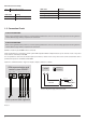
1.6 System Installation The system can be installed only in a metal or non-flammable plastic enclosure. If the metal enclosure and transformer is used it is necessary to ground the enclosure using yellow/green colour cable. For the connection of 230V transformer use 3x0.75 mm2 1 thread double isolated cable. The primary circuit of the transformer must be connected through 0.5A fuse. 230V power supply cables cannot be grouped with low voltage cable group.
2. System Pre-operation and the Main Control Commands VERY IMPORTANT!!! Underscore symbol ‘_’ in this manual is used to represent space. When writing SMS messages, every underscore symbol should be replaced by single space symbol. XXXX – means password. Don’t leave any space at the beginning and the end of the message. To set ESIM251 system parameters easier and quicker you can use the computer, USB cable and configuration software „ELDES Configuration Tool“. You can read more in chapter 3.2. 2.
2.3 User Numbers The system ESIM251 allows to pre-program up to five different mobile numbers which will have access to and control the system. NR1 is mandatory while others can be skipped. All numbers must be entered starting with international country code, e. g. national code for Lithuania is 370, UK – 44. By default the system starts sending all messages and in the event of alarm starts calling on the first number, and if the first call is unsuccessful, it immediately tries reaching subscriber No2 etc.
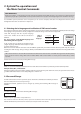
3. Additional System Capabilities 3.1 Renaming alarm, restore text and controller names Manufacturer initially set the following zone and controlled output names: Zone1, Zone2, Zone3, Zone4, Zone5, OUTPUT1 E. g. if during the alarm Z1 zone was triggered, the system sends SMS message with the text: Zone1 Alarm text changes are made by sending the following SMS message: XXXX_Z1:NewAlarmText;Z2:NewAlarmText;Z3:NewAlarmText;Z4:NewAlarmText;Z5:NewAlarmText; E. G.
Disabling Zone Any zone can be disabled by sending the following SMS message: XXXX_Z1:OFF;Z2:OFF;Z3:OFF;Z4:OFF;Z5:OFF; ESIM 251 XXXX_ WINDOWS: OFF; E. g. XXXX_Z2:ON; or XXXX_WINDOWS:ON; or XXXX_Z2:OFF; or XXXX_WINDOWS:OFF; 3.3 Info on Status SMS The system ESIM251 can any time be inquired about signal strength and the status of zones active at the time when SMS message is sent. At the same time system test is performed. If the answer to the request has been received, it means the system finely operates.
3.5 Remote Microphone Listening NOTE To enable this feature it is necessary to connect microphone connector to MIC slot. The microphone is additional equipment tha can be purchased in trading centers. You can listen to what is going on in the secured premises by sending the following SMS message: XXXX_MIC The system will ring the sender of the received SMS, and upon answering the call, the user can listen to any sounds in the building.
To enable this function send the following SMS message: XXXX_SMSALL:ON To disable this function send the following SMS message: XXXX_SMSALL:OFF If you want to configure SMS message delivery only for particular users or only for particular zones, refer to chapter 3.9 or use configuration program. 3.8 Calling all users During the alarm, ESIM251 system starts calling NR1. If the call to NR1 was unsuccessful or the subscriber was out of network coverage the call is forwarded to NR2 etc.
F O R A D VA N C E D U S E R S All these features can be configured using program “ELDES Configuration Tool“ E. g. 1 The user wants to connect ESIM251 system to an existing alarm in a building where enterprise A and and enterprise B work. Both enterprises use the same alarm system that has two zones.The alarm system has 5 programmable outputs (PGM).
F O R A D VA N C E D U S E R S All these features can be configured using program “ELDES Configuration Tool“ Task NO2: Configuring the system so that the janitor (NO3) is informed about the triggered perimeter sensor of field territory by SMS message and a call; and when the sensor is reset, the janitor receives SMS message only.
F O R A D VA N C E D U S E R S All these features can be configured using program “ELDES Configuration Tool“ E. g. 1 The user wants to connect ESIM251 system to an existing alarm in a building where enterprise A and and enterprise B work. Both enterprises use the same alarm system that has two zones.The alarm system has 5 programmable outputs (PGM).
F O R A D VA N C E D U S E R S All these features can be configured using program “ELDES Configuration Tool“ Task NO4: Configuring the system so that the intrusion to enterprise B premises is reported to the janitor (NO3) and enterprise B employee (NO5) by SMS messages and calls, and the director of enterprise B (NO2) receives SMS message only. Enterprise B employee (NO5) must receive the phone call even in the case when the janitor (NR3) answers the call.
F O R A D VA N C E D U S E R S All these features can be configured using program “ELDES Configuration Tool“ E. g. 2. The user wants to connect ESIM251 system to the programmable outputs (PGM) of an existing alarm system. House territory is entered through electrically controlled gates. There are 5 users in total. NO1 is the housekeeper, NO2 is a neighbour, NO3-NO5 are family members.
F O R A D VA N C E D U S E R S All these features can be configured using program “ELDES Configuration Tool“ Task NO2: Configuring the system so that house gates could be opened via free calls by the housekeeper (NO1) and his family members (NO3), (NO4) and (NO5). After every successful gate opening the user NO5 wants to receive a confirmation call (CALLBACK) the duration of which is 3 seconds, and the user NO3 wants to receive a confirmation SMS message.
F O R A D VA N C E D U S E R S All these features can be configured using program “ELDES Configuration Tool“ E. g. 3. The user wants to connect ESIM251 system to the heating system of the house. Task No1: Configuring the system so that house heating system is turned on and turned off by the user (NO1) via free call. This user should also receive free information abut successful turning on or turning off of the heating system.
F O R A D VA N C E D U S E R S All these features can be configured using program “ELDES Configuration Tool“ Task No2: Configuring the system so that users (NO1) and (NO2) receive SMS message about a burst water pipe (flood) at home. SMS messages must be delivered to both users.
F O R A D VA N C E D U S E R S All these features can be configured using program “ELDES Configuration Tool“ E. g. 4. The company taking care of automatic systems needs to have information about critical breakdowns of mechanisms and has to quickly react and eliminate the breakdown. There are three members of operating personnel (NO1), (NO2) and (NO3). Task No1: Configuring the system so that operating personnel member (NO1) receives SMS message about the breakdown of gas boiler.
F O R A D VA N C E D U S E R S All these features can be configured using program “ELDES Configuration Tool“ Task No2: Configuring the system so that the operating personnel member (NO2) receives SMS message if the pump was triggered for 10 times.
F O R A D VA N C E D U S E R S All these features can be configured using program “ELDES Configuration Tool“ E. g. 4. The company taking care of automatic systems needs to have information about critical breakdowns of mechanisms and has to quickly react and eliminate the breakdown. There are three members of operating personnel (NO1), (NO2) and (NO3).
F O R A D VA N C E D U S E R S All these features can be configured using program “ELDES Configuration Tool“ 3.9.1 Additional possibilities of configuring zones (inputs) alarm and restore Initial factory default settings. During the alarm the system calls and sends SMS messages to all pre-programmed users until the first successful SMS delivery or a call rejected by the user. The users are not notified about zone restore. Zone delay due to interference is 600ms – i. e.
F O R A D VA N C E D U S E R S All these features can be configured using program “ELDES Configuration Tool“ ATTENTION! Value fields are separated by commas. Maximum SMS length is 160 characters. Only one zone parameters can be configured by one SMS message. Examples of using SMSEXTRA command. Suppose in all cases initial parameters were not changed and are manufacturer default. 1.
F O R A D VA N C E D U S E R S All these features can be configured using program “ELDES Configuration Tool“ 3.9.2 Additional possibilities of controlling and configuring controller C1 (relay output) Normally C1 output can be controlled only by SMS message, as described in chapter 3.6, i. e. by enabling/disabling it for a permanent status or for a preset period. However, you can configure automatic enabling and disabling for a particular hour or control this function by a call. 3.9.2.
F O R A D VA N C E D U S E R S All these features can be configured using program “ELDES Configuration Tool“ Type of control via call Setting relay impulse duration MS MS 1,2,3,4,5 and 0 When users No:1,2,3,4,5 call the output is enabled. 1,2,3,4,5 and 1 When users No:1,2,3,4,5 call the output is disabled. 1,2,3,4,5 and 2 When users No:1,2,3,4,5 call output status is changed (TOGGLE) 1,2,3,4,5 and Th.m.s Setting relay impulse duration for users No:1,2,3,4,5. h- hours, m- minutės, sseconds.
F O R A D VA N C E D U S E R S All these features can be configured using program “ELDES Configuration Tool“ Value (CnVal) – table of values Cn – command name (2 letters) Val – possible command meaning. Command description CB 1 Confirmation call mode is enabled for all users. CB 0 Confirmation call mode is disabled for all users.
F O R A D VA N C E D U S E R S All these features can be configured using program “ELDES Configuration Tool“ 3.9.2.3 Output ontrol settings by event time This chapter describes a possibility to control C1 output (relay) using timetable (schedule). It can be, for instance, atomatic turning on every day at 18:00 and turning off after 5 hours. The parameters are changed by sending the following SMS message to the system ESIM251: XXXX_SMSEXTRA:OCTE:Value1,Value2,……,ValueN XXXX – user password.
F O R A D VA N C E D U S E R S All these features can be configured using program “ELDES Configuration Tool“ Setting the user who receives confirmations about period start/end Setting confirmation SMS message for period start Setting confirmation SMS message for period end UC 0; s The user receives a confirmation call when the output is disabled; s- call time in seconds СT08 The first digit is a command; the last digit refers to call time in seconds. E. g.
4. Appendix 4.1 Restoring Default Parameters To restore default parameters: • disconnect power supply and USB connector • short circuit (connect) connectors D1 and D2 • connect power supply for 5 seconds • disconnect power supply • disconnect connectors D1 and D2 4.2 “ELDES Configuration Tool“ Software To confi gure the system quicker and easier as well as use more system capabilities use configuration software “ELDES Configuration Tool“ which can be downloaded from our website www.eldes.
USER MANUAL ELDES ESIM251 V1.
For notes 34
For notes USER MANUAL ELDES ESIM251 V1.
Made in Lithuania. www.eldes.