
Data Sheet

ITG-3200 Product Specification
Document Number: PS-ITG-3200A-00-01.4
Revision: 1.4
Release Date: 03/30/2010
16 of 39
5 Functional Overview
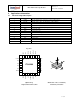
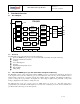
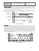
5.1 Block Diagram
VDD
CLOCK
ITG-3200
Charge
Pump
AD0
SCL
SDA
Temp
Sensor
ADC
ADCY Gyro
Signal
Conditioning
ADCX Gyro
Signal
Conditioning
Bias & LDO
1
9
23
24
I
2
C Serial
Interface
GND REGOUT
Config
Register
Clock
CPOUT
Interrupt
INT
12
Sensor
Register
20
13 18 10
Interrupt
Status
Register
VLOGIC
8
Optional
ADCZ Gyro
Signal
Conditioning
Factory Cal
FIFO
5.2 Overview
The ITG-3200 consists of the following key blocks and functions:
Three-axis MEMS rate gyroscope sensors with individual 16-bit ADCs and signal conditioning
I
2
C serial communications interface
Clocking
Sensor Data Registers
Interrupts
Digital-Output Temperature Sensor
Bias and LDO
Charge Pump
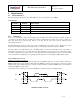
5.3 Three-Axis MEMS Gyroscope with 16-bit ADCs and Signal Conditioning
The ITG-3200 consists of three independent vibratory MEMS gyroscopes, which detect rotational rate about the X
(roll), Y (pitch), and Z (yaw) axes. When the gyros are rotated about any of the sense axes, the Coriolis Effect causes a
deflection that is detected by a capacitive pickoff. The resulting signal is amplified, demodulated, and filtered to
produce a voltage that is proportional to the angular rate. This voltage is digitized using individual on-chip 16-bit
Analog-to-Digital Converters (ADCs) to sample each axis.
The full-scale range of the gyro sensors is preset to ±2000 degrees per second (°/s). The ADC output rate is
programmable up to a maximum of 8,000 samples per second down to 3.9 samples per second, and user-selectable low-
pass filters enable a wide range of cut-off frequencies.