
Data Sheet

ITG-3200 Product Specification
Document Number: PS-ITG-3200A-00-01.4
Revision: 1.4
Release Date: 03/30/2010
23 of 39
8 Register Description
This section details each register within the InvenSense ITG-3200 gyroscope. Note that any bit that is not defined
should be set to zero in order to be compatible with future InvenSense devices.
The register space allows single-byte reads and writes, as well as burst reads and writes. When performing burst reads
or writes, the memory pointer will increment until either (1) reading or writing is terminated by the master, or (2) the
memory pointer reaches certain reserved registers between registers 33 and 60.
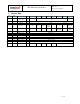
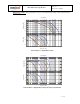
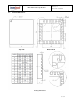
8.1 Register 0 – Who Am I
Type: Read/Write
Register
(Hex)
Register
(Decimal)
Bit7
Bit6
Bit5
Bit4
Bit3
Bit2
Bit1
Bit0
0
0
-
ID
-
Description:
This register is used to verify the identity of the device.
Parameters:
ID Contains the I
2
C address of the device, which can also be changed by writing to this register.
The Power-On-Reset value of Bit6: Bit1 is 110 100.
8.2 Register 21 – Sample Rate Divider
Type: Read/Write
Register
(Hex)
Register
(Decimal)
Bit7
Bit6
Bit5
Bit4
Bit3
Bit2
Bit1
Bit0
Default
Value
15
21
SMPLRT_DIV
00h
Description:
This register determines the sample rate of the ITG-3200 gyros. The gyros outputs are sampled internally at
either 1kHz or 8kHz, determined by the DLPF_CFG setting (see register 22). This sampling is then filtered
digitally and delivered into the sensor registers after the number of cycles determined by this register. The
sample rate is given by the following formula:
F
sample
= F
internal
/ (divider+1), where F
internal
is either 1kHz or 8kHz
As an example, if the internal sampling is at 1kHz, then setting this register to 7 would give the following:
F
sample
= 1kHz / (7 + 1) = 125Hz, or 8ms per sample
Parameters:
SMPLRT_DIV Sample rate divider: 0 to 255