
User Manual


10 ELECRAFT
Desoldering
The printed circuit boards used in the kit are double-sided, meaning
that they have circuitry on both sides. The component mounting
holes are plated-through to complete electrical connections
between the two sides.
Removing components from double-sided boards can be difficult,
since you must get all of the solder back out of the hole before a
lead can be removed. To do this, you'll need solder wick
(desoldering braid) and/or a vacuum desoldering tool. It also takes
some practice. A number of suggestions are provided below.
The best strategy for avoiding de-soldering is to place all
components properly the first time. Double-check values
and orientations, and avoid damaging parts via ESD.
When removing components:
Don't pull a lead or pin out of a hole unless the solder has been
removed, or you are applying heat. Otherwise, you can literally
pull out the plating on the plated-through hole.
Limit soldering iron contact to a few seconds at a time.
Use small-size solder-wick, about 0.1" or 2.5 mm wide. Use the
wick on both the top and bottom pads when possible. This
helps get all of the solder out of the hole.
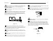
If you use a vacuum desoldering tool (solder sucker), use a large
unit. Small solder suckers are not very effective.
The safest way to remove ICs and other components with more
than 3 leads is to clip all of the pins at the body of the device
first, then remove all of the pins individually. You may damage
pads and traces by trying to remove such components intact.
Invest in a PC board vice with a heavy base if possible. This
makes parts removal easier because it frees up both hands.
If in doubt about a particular repair, ask for advice from Elecraft or
from someone else with PCB repair experience.
Assembly Notes
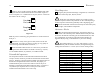
Each step in the assembly process is accompanied by a check-box:
This symbol is used to alert you to important information:
i
Do not skip any steps. You may adversely affect both the
performance and appearance of the kit by using the wrong
assembly order.
Components
Sometimes we refer to components by their PC board and reference
designator. For example, "FP-Q1" refers to transistor Q1 on the
Front Panel board.
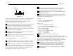
A few components in the kit are mounted on the bottom of PC
boards. Component outline symbols are provided on the
appropriate side of the board, so it will always be clear which side a
particular component goes on. Bottom-mounted parts are also
identified on the schematics by this symbol:
Photographs
Before beginning assembly, you should review the photographs in
Appendix D to get an idea of what the completed PC boards look
like. You'll also find front and back views of each PC board in the
Parts Placement Drawings, Appendix F.