
User Manual


ELECRAFT 11
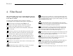
4. Filter Board
This section applies only to the two-band K1 Filter board. If
you have a four-band K1, refer to the assembly instructions
in the KFL1-4 manual.
The Filter board determines the K1's bands of operation.
A photograph of the completed board appears in Appendix D.
Open the bag of components labeled KFL-2 and
sort the parts into groups. Identify components using the
photographs in the Filter board parts list in Appendix A.
Locate the Filter printed circuit board (PCB), labeled "K1
FIL2" on one side.
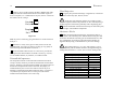
With the top side of the PC board facing you (notch at the
lower right), locate the position of resistor R1, along the front
edge. The label "R1" appears just left of the resistor’s outline.
Install a 100-ohm, 5% resistor (brown-black-brown) at R1,
with its first color band (brown) toward the left. Make sure it is
seated flat on the board, then bend the leads outward at about a 45-
degree angle to hold it in place.
Solder R1 on the bottom of the board. Trim the leads as close
as possible to the solder joints.
i
Components may be soldered one at a time or in groups.
Leads can be trimmed either before or after soldering.
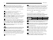
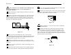
Install an 18-pin IC socket at U1, with the notched end of the
socket oriented towards the "K1 FIL2" label. Bend two leads of the
socket outward slightly to hold it in place while soldering. (U1 itself
will be installed in a later step.)
i
In the following steps you'll install three relays (K1-K3).
Relay pins must not be bent, even after placement on the PC board,
as this may cause unreliable mechanical operation.
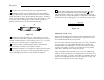
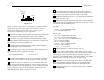
Place relays K1-K3 on the top side of the board. One end of
each relay has a heavy line printed across the top to indicate the
pin 1 end. This end must be matched with the same end of the
relay’s PC board outline. Do not solder the relays yet.
When all three relays have been placed on the board, lay a flat
object such as a book or piece of cardboard on top of the relays to
keep them in place, then flip the board over.
Solder only two pins (at opposite corners) on each relay, using
a minimum amount of solder. Limit soldering time to 2 or 3
seconds per pin. Do not bend or trim the leads.
Turn the board back over and verify that all of the relays are
in the correct orientation and are seated flat on the board. To
check the orientation, refer to the Filter board drawing in
Appendix F, at the bottom of the page.
Solder all of the remaining relay pins. Do not bend or trim the
leads.