
User Manual


ELECRAFT 47
Band 1 Alignment
If a 4-band Filter board is in use, refer to the KFL1-4 manual, page 19.
All filters are shared between receiver and transmitter, so transmit
alignment should already be close. However, it's important to re-
peak the filters on transmit. An analog wattmeter, ham-band
receiver, or the K1’s built-in digital wattmeter can be used.
Switch to lower-frequency band using B A N D . Set the VFO to
approximately the middle of the desired band.
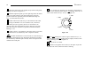
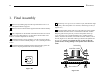
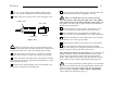
Refer Figure 7-2 to identify the band 1 inductors.
i
The K1 can be placed in TUNE mode by holding the
W P M + and W P M - switches together. During TUNE, the power in
watts will be shown on the LCD (e.g., P 2 . 0 ). Hitting the key or
pressing any switch except
W P M + and W P M - will cancel TUNE.
Put the K1 into TUNE mode. Using the alignment tool, adjust
L1, L2, L5 and L6 for maximum output. If the output jumps up to
well above 2 watts, exit TUNE mode, then re-enter it again.
3
If necessary, repeat the adjustment of the filters two or three
times to be sure that you have the inductors peaked correctly. If
output is < 2 w or is not stable, see Troubleshooting.
If possible, verify that the K1 is transmitting on the correct
frequency using an external ham-band receiver. Connect a short
length of wire to the receiver's antenna jack. (Do not connect the
K1 directly to the receiver.) Key the K1 and locate the signal.
To make sure that the filters are peaked at the correct
frequency, vary each inductor a small amount while observing the
receiver's S-meter.
3
The transmitter's ALC (automatic level control) attempts to set the power
you specify. ALC is activated for 1-2 seconds when you enter TUNE mode.
After that, it is "open-loop," allowing you to adjust the filters. If the power
jumps, re-starting TUNE mode will activate the ALC again, reducing the
drive back down to the level needed to stay at about 2 watts.
Band 2 Alignment
Switch to band 2, and set the VFO to about mid-band.
Put the K1 into TUNE mode and adjust L3, L4, L7, and L8
for maximum output (refer to Figure 7-2 if necessary).
Verify that the K1 is transmitting at the intended frequency.
5-watt Test
Set power output to 5 . 0 watts using the O U T menu entry.
Enter TUNE mode briefly. The wattmeter should display
approximately 5 watts. Test 5-watt output on both bands.
Transmit Offset Adjustment
Locate the offset test switch (S2) on the bottom of the RF
board. Place it in the TEST position. You should hear a tone in the
headphones; its pitch is equal to the transmit offset. If you don’t
hear a tone, try rotating C13 (back left corner, near the key jack).
Using the menu, locate S T P (sidetone pitch), and go into edit
mode to turn on the sidetone. You should now hear two tones: the
sidetone and the transmit offset tone. If the sidetone is very weak
or very strong compared to the transmit offset tone, use the S T L
menu entry to adjust the sidetone volume. Note: The receiver is
muted in S T L edit mode, so you'll have to return to S T P after
making any change to the sidetone setting.
Adjust C13 so that the transmit offset pitch is as close as
possible to your selected sidetone pitch. The two will seem to
"merge" when the pitches are matched.
Exit the menu, and set S2 back to the OPER position.
If necessary, use the C A L menu entry to calibrate the
operating frequency on transmit (see page 41).
This completes transmitter alignment.