User Guide V2.0 C 2020.02 2020 ELECROW All Rights Reserved. www.elecrow.
Content Instruction Crowduino Uno Crowtail Modules List Getting Started 01 02 02 04 05 ● Installing IDE 05 ● How to upload program 08 ● Add Libraries and Open Serial Monitor 09 Lessons 11 ● Lesson 1 – LED Control 11 ● Lesson 2 – Button Control LED 12 ● Lesson 3 – Switch LED 14 ● Lesson 4 – Touch reminder 15 ● Lesson 5 – Tilt Alarm 17 ● Lesson 6 – Flame Alarm 18 ● Lesson 7 – Breathing LED 20 ● Lesson 8 – Moisture Monitor 22 ● Lesson 9 – Sound Reminder 23 ● Lesson 10 –
Instruction Welcome to the Crowtail-Starter kit for Arduino user guide. Here we are going to get started with some of the basics sensors and hardware with Arduino or Crowduino. Don't worry, this kit contains 20 interesting and instructive tutorials, from simple to difficult, step by step to familiarize you with electronic modules, exercise your logical thinking and develop your ideas, and finally use electronic modules through programming.
Crowduino Uno The Crowduino Uno-SD mainboard is a microcontroller board that completely compatible with the Arduino UNO. It is based on the Atmega328P, which is widely also used in the Arduino Uno and other Arduino compatible boards.
1 11 Digital I/O ports (D2~D12) that have a mark “D”. These ports can be used to read and control digital Crowtail modules (Crowtail modules that have a mark “D”), such as the Button and LEDs. Some of the digital I/O ports can also be used as PWM (pulse width modulation) outputs; 2 6 Analog ports (A0~A5) that have a mark of “A”. Besides the functional of digital, these A ports can read the analog signal, such as a potentiometer or light sensor; 3 3 UART ports that have a mark of “U”.
Modules List ● Crowduino Uno-SD x1 ● Crowtail - Base Shield x1 ● Crowtail - Button x1 ● Crowtail - Switch x1 ● Crowtail - Buzzer x1 ● Crowtail - LED(Red) x1 ● Crowtail - LED(Green) x1 ● Crowtail - LED(Yellow) x1 ● Crowtail - Logic AND x1 ● Crowtail - Logic OR x1 ● Crowtail - Logic NOT x1 ● Crowtail - Flame Sensor x1 ● Crowtail - Moisture Sensor x1 ● Crowtail - Touch Sensor x1 ● Crowtail - Relay x1 ● Crowtail - Light Sensor x1 ● Crowtail - Thermistor Temperature Sensor x1 ●
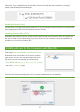
Getting Started Installing IDE Introduction "Arduino" is not only the name of the microcontroller board but also the name of a programming IDE based on C/C++. After you get your Arduino board or compatible board such as Crowduino, you should install the IDE. Depending on the OS version, the specific installation varies. The Arduino software that you will use to program your Arduino is available for Windows, Mac, and Linux. In this lesson, you will learn how to set up your computer to use Arduino.
Click “Install” to initiate installation. Then when finished, the Arduino icon will appear and like this Connect Arduino/Crowduino to PC. Connect the Arduino/Crowduino board to your computer by using the USB cable. Install Driver Installing drivers for the Crowduino In Windows. Plug in your Crowduino, Windows will try to install the driver automatically. If you are lucky enough, the installation will be done automatically in about 1 minute. If not, follow the next steps.
Click Next, if you installed driver successfully, Check with serial port the Crowduino is using by opening the Windows Device Manager. Installing Arduino (Linux) You will have to use the make install command. If you are using the Ubuntu system, it is recommended to install Arduino IDE from the software center of Ubuntu. Installing Arduino (Mac OS X) Download and Unzip the zip file, double click the Arduino.
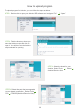
How to upload program To upload program for Arduino, you can follow the steps as below. STEP1: Double click to open your Arduino IDE software and navigate “File” › “Open” STEP2: Find the directory where you store the Arduino script and click to open it. You will then see the Arduino script selected for opening. STEP3: Select the board for your Arduino, Select Tools Board Arduino/Genuino Uno.
STEP5: Click the upload icon to upload the program. STEP6: After the program is uploaded, you will see the upload success prompt. Add Libraries and Open Serial Monitor What are libraries? Libraries are a collection of code that makes it easy for you to connect a sensor, display, module, etc. There are hundreds of additional libraries available on the Internet for downloading. To use the additional libraries, you will need to install them.
Arduino Serial Monitor (Windows, Mac, Linux) The Arduino IDE is the software side of the Arduino platform, for it is a big part of working with Arduino and other microcontrollers, so the software includes a serial terminal. It is called the serial monitor within the Arduino environment. The Serial Monitor is one of the Arduino IDE's many great built-in tools.
You can set the terminal to autoscroll or not by checking the box in the bottom left corner. Lessons Lesson 1 – LED Control Introduction "Arduino" is not only the name of the microcontroller board but also the name of a programming IDE based on C/C++. After you get your Arduino board or compatible board such as Crowduino, you should install the IDE. Depending on the OS version, the specific installation varies.
What will you see The LED will light for one second and off for one second, then repeat. If not, be sure to connect the LED module correctly to the Crowtail-Base Shield interface. Code overview and usage Lesson 2 – Button Control LED Introduction This momentary button output logic HIGH signal when pressed and logic LOW signal when released.
Hardware Connection STEP1: Plug the Crowtail- Base Shield onto the Arduino or Crowduino Board. STEP2: Connect Crowtail-Button to Crowtail-Base Shield D4 port and Crowtail-LED to D5 port. The complete connection is as follows: Open the P02_Button_Control_LED with Arduino IDE and upload it. What will you see If you press the button, the LED will light on, and it will light off when you release the button.
Lesson 3 – Switch LED Introduction The Crowtail- Switch is a Latching switch. When the switch is pressed for the first time, the switch maintains current regulation and the button outputs a HIGH signal in the self-locking state. When the switch is pressed for the second time, the switch button pops up and the switch turns off and then outputs a LOW signal.
Code usage Integer Variables: int switchPin=4; int ledPin=5; A variable is a placeholder for a value that may change in your code. Variables must be introduced or "declared" before using variables. Here, we declare a variable called ‘ledPin’ and ‘switchPin’ of type int(integer) and assign it a value of 5 and 4, that is, led corresponds to pin 5 while switch corresponds to pin 4.
Required Parts Crowduino UNO-SD x1 Crowtail – Base Shield x1 Crowtail – Touch Sensor x1 Crowtail – Cable x2 Crowtail – Vibration Motor x1 USB Cable x1 Hardware Connection STEP1: Plug the Crowtail-Base Shield onto the Arduino or Crowduino Board. STEP2: Connect Crowtail-Touch sensor to Crowtail-Base shield’s D4 and Crowtail-Vibration motor to D5 port. The complete connection is as follows: Open the P04_Touch_Reminder with Arduino IDE and upload it.
Loop: void loop(){code to run forever} Firstly, for the reason that the touch sensor is a digital module, we use the digitalRead() function to read the touch sensor value, then use the if/else statement to determine if the touch sensor is touched(HIGH) or not touched(LOW). If it is touched, let the vibration sensor vibrate, otherwise, the vibration sensor will not vibrate. Lesson 5 – Tilt Alarm Introduction The Crowtail-Tilt Switch is a sensor to detect the station of forwards.
What will you see Let the tilt sensor lie flat. When you tilt the sensor to the left, logic high signal will be output and the buzzer will beep. When you tilt the tilt sensor back or right, logic low signal will be output and the buzzer will stop sounding. Code usage Integer Variables: int tiltPin = 4; int buzzerPin = 5; int tiltState = 0; Here, we declare three variables tiltPin, buzzerPin and tiltState and assign values to them.
Required Parts Crowduino UNO-SD x1 Crowtail – Base Shield x1 Crowtail – Flame Sensor x1 Crowtail – Cable x3 Crowtail – Buzzer x1 USB Cable x1 Crowtail – LED x1 Hardware Connection STEP1: Plug the Crowtail-Base Shield onto the Arduino or Crowduino Board. STEP2: Connect the Crowtail-Flame sensor, Crowtail-Buzzer and Crowtail-LED to the D4, D5 and D6 ports of the Crowtail-Base shield. The complete connection is as follows: Open the P06_Flame_Alarm with Arduino IDE and upload it.
In the setup() method, we need to initialize the flame sensor as an input to detect whether a fire has occurred, and initialize the buzzer and led as outputs respectively to make the buzzer beep and led to flash when a fire is detected. Digital Input: flameState = digitalRead(flamePin); Like other digital input modules, We use the digitalRead() function to read the value on flame sensor. Check that the flame sensor reading is HIGH(5V) or LOW(0V).
Open the P07_Breathing_LED with Arduino IDE and upload it. What will you see When you move the slider on Linear Potentiometer, you can see the change of LED brightness. If you move the slider to the far left of the sliding rheostat closest to the Crowtail connector, the LED is the darkest and then the LED should be the brightest when you move the slider to the far right.
Analog Input: analogWrite(ledPin, gapValue); For analog pin, we use the analogWrite() function to write the value on an analog pin. Similar to digitalWrite() function, it takes two parameters, But the second parameter is no longer only two high and low states, it can be any number you want to write, and each value you write will give it the corresponding state. But in fact, there is a premise, that is, the hardware must be able to divide so many levels of effect. For example, most of the led is 256.
Open the P08_Moisture_Reminder with Arduino IDE and upload it. What will you see Open the Serial monitor, if you put the Moisture in the air, You can see that the value detected by the Moisture sensor printed by the serial monitor is 0. When you put it in the soil or water, You can see that the value keeps increasing and then reaches a continuous value.
Crowtail-Sound Sensor can detect the sound loudness of the environment. The main component of the module is a simple microphone to receive the sound signal, with band pass filter and a LMV358 amplifier to make the output signal easy to be received by microprocessor. This module outputs an analog signal that shows the relative loudness. Besides, an on-board potentiometer can be used to adjust the output voltage.
If/else Statements: if(logic statement) {code to be run if the logic statement is true} else {code to be run if the logic statement is false } In the if / else statement, if the soundValue is greater than 500, we let the buzzer sound for one second, then loop () to determine if the soundValue is still greater than 500, and if so, the buzzer will continue to beep. Otherwise, the buzzer will stop beeping.
What will you see In the daytime, use your hand to block the top of the light sensor, you will see that the led will automatically light up. When you remove your hand, the led will automatically go out. You can also observe the difference between day and night, and then make an energy-saving light for your home! Code usage Integer Variables: int lightPin = A0; int ledPin = 5; int lightValue = 0; Define the lightPin connect to A0 port of the Crowtail-Base shield and ledPin to D5 port.
Required Parts Crowduino UNO-SD x1 Crowtail – Buzzer x1 Crowtail – Base Shield x1 Crowtail – Cable x2 Crowtail – Thermistor Temperature Sensor x1 USB Cable x1 Hardware Connection STEP1: Plug the Crowtail-Base Shield onto the Arduino or Crowduino Board. STEP2: Connect Crowtail-Thermistor temperature sensor to Crowtail-Base shield’s A0 and Crowtail-Buzzer to D5 port. The complete connection is as follows: Open the P11_Overheat_Alarm with Arduino IDE and upload it.
Lesson 12 – Logic NOT Introduction What is logic gate? In digital circuit applications, a logic gate is a basic logic component that acts as a switch. Under certain conditions, it can determine whether the signal passes or does not pass. A simple logic gate can be made up of transistors that perform a logic operation on the input level signal and then generate a high or low level signal. Logic gates are the basic structure of digital circuit systems.
What will you see After uploading the program, you will see the LED light up! This is too strange, because in the code we let the led light be on when the touch sensor is touched, but now the touch sensor is not touched at all. Don't be surprised, this is because the Logic NOT module's inverse action, when the touch sensor is not touched, our program does output a logic low level, but after the Logic NOT module is inverted, the output will become high. So, the light is lit.
Required Parts Crowduino UNO-SD x1 Crowtail – Switch x1 Crowtail – Base Shield x1 Crowtail – Vibration Motor x1 Crowtail – Logic OR x1 Crowtail – Cable x5 Crowtail – Button x1 USB Cable x1 Hardware Connection STEP1: Plug the Crowtail-Base Shield onto the Arduino or Crowduino Board. STEP2: Connect Crowtail-Switch and Crowtail-Button to Crowtail-Base shield’s D3 and D4 port. Connect Crowtail-Logic OR A port and Crowtail-Logic OR B port to D7 and D8 port.
Lesson 14 – Logic AND Introduction The logic AND can gives you more ability to create interesting and complex interactions. It has two inputs and one output, the interface of the logic AND is a digital interface, it will output a logic-high or logic-low signal. Different from the logic OR module, the logic AND module only output a logic-high signal when both of the inputs are logic-high. Otherwise, the AND will output a logic-low signal.
What will you see If you put this project in a very bright environment, no matter how loud your sound is, the LED will not light up. Also, if you put it in a very quiet environment, no matter how dark your environment is, the LED will not light up. Because under the function of the Logic AND module, the two inputs must be at the same logic high level to output a logic high level. Is it amazing? The Logic AND module helps me to handle different events.
The connector of the relay module has three sockets: common (COM), normally closed (NC), and normally open (NO). COM: common pin. NC (Normally Closed): the normally closed configuration is used when you want the relay to be closed by default, meaning the current is flowing unless you send a signal to the relay module to open the circuit and stop the current. NO (Normally Open): the relay is always open, so the circuit is broken unless you send a signal to close the circuit.
What will you see If your current ambient temperature is not 30 degrees Celsius, the LED will not turn on, otherwise, the LED will automatically turn on. If your environment does not reach 30 degrees Celsius, but you want to test whether the project is working, you can blow against the Thermistor Temperature Sensor and let it detect temperatures greater than 30 degrees Celsius. Code usage Math Library: #include
STEP2: Connect Crowtail-4-Digit Display to Crowtail-Base shield’s I port. The complete connection is as follows: Open the downloaded folder “Crowtail-Starter kit for Arduino demo code”, navigate to the folder lib-> U8glib, and add U8glib to the Arduino library. If you don't know how to add it, you can skip to the "Add Libraries and Open Serial Monitor" category and check out the tutorial. Open the P16_Show_Number_ On_4-Digital_display with Arduino IDE and upload it.
Digital Display: DigitalLED.display(Number of digits, display content); This is the function of the “TM1650.h” library, which is used to display the number or char of the 4-Digit display module. This function has two parameters, the first one is the number of digits in the digital tube and the second one is the number or character that needs to be displayed. Lesson 17 – Traffic light Introduction We have already finished learning all the modules, let us try to do some interesting projects.
Code usage 4-Digit Display library: #include "TM1650.h" “TM1650.h” is a 4-digit display library with very comprehensive use of functions for calling and using this module. Therefore, we should first import TM1650.h library so that its function can be used to call the 4-Digit display.
In this course, we will use sound and light sensors to detect sound and brightness. When the day is dark and the sound is detected, the light will automatically turn on to illuminate. In addition, we have added another function to this corridor light, which is to help the elderly function, because the elderly may not have good eyesight and maybe too dark for them during the day, so we hope to use a touch switch to help them. When they feel too dark, they can turn on the light by pressing the touch sensor.
we usually add Value to the variable name as the end. Here, we declare that sound sensor and light sensor are connected to analog ports A0 and A1, touch sensor and LED are connected to digital ports D4 and D5, and then all values to be used are assigned to zero.
Open the P19_Plant_Watering_Reminder_System with Arduino IDE and upload it. What will you see The moisture value read by the moisture sensor will be divided into three stages. The 4-digit display will show moisture value at any stage. The first stage is the extreme water shortage with a moisture value of less than 10%. At this time, the buzzer will beep loud to prompt water it immediately. The second is a slight water shortage with a moisture value between 10% and 20%.
Divisor and remainder: t = moistureValue/10; d = moistureValue%10; “t” and “d” represent the tens and single digits of the moistureValue we want to get. When the moistureValue is a two-digit number and you want to get a ten-digit value, we only need to divide the moistureValue by 10, and the result is a ten-digit value, such as 52/10=5. If you want to get a single digit value, we only need to use the moistureValue to take the remainder of 10 to get the single digit value, such as 52%10=2.
STEP2: Connect 4-Digit Display to Crowtail-Base shield’s I port. Connect Crowtail-LED(Red) and Crowtail–Linear Potentiometer to D5 and A0 port. The complete connection is as follows:Connect Crowtail-LED(Red), Crowtail-LED(Green) and Crowtail-Buzzer to D2, D3 and D5 port. The complete connection is as follows: Open the P20_Brightness_Display with Arduino IDE and upload it.