
GAS CHOPPER SCOOTER Assembly and User's Manual 88905, 88969


9
ASSEMBLY INSTRUCTIONS
BEFORE ASSEMBLING YOUR GAS CHOPPER SCOOTER
TM
, PLEASE BE SURE YOU HAVE ALL NECESSARY
PARTS. REFER TO CONTENT OF BOX. PLEASE FOLLOW PROPER ASSEMBLY INSTRUCTIONS. IF YOU DO
NOT HAVE THE PROPER PARTS NECESSARY TO ASSEMBLE YOUR GAS CHOPPER SCOOTER
TM
, PLEASE
DO NOT RETURN THE UNIT TO THE ORIGINAL PLACE OF PURCHASE. CALL ELECTRA CUSTOMER
SERVICE AT: 1-888-467-1234 M-F 10am - 9pm EST.
*For convenience of packing and shipping, the handlebars, throttle, accessory control grip and
backrest are not assembled on your GAS CHOPPER SCOOTER™. They must be properly adjusted
and tightened before riding.
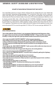
HANDLEBAR INSTALLATION
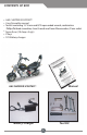
1. Remove the GAS CHOPPER SCOOTER™ from the carton and remove all protective packaging
2. Lift the handlebar assembly to an upright position and tighten the fastening knob so that it
secure. (Fig. 1)
3. Unscrew and remove the bolts located on the front of the handlebar assembly. Align the
instrument gauge assembly on the bracket and fasten by inserting the bolts and tightening.
4. Insert the throttle into the handlebar assembly by depressing the copper colored button and
aligning it with its seated hole. Insert until the throttle locked in position. Repeat this procedure
with the left accessory control grip. Secure the throttle and accessory control grip by tightening the
allen bolts located directly below the copper colored buttons. (Fig. 2)
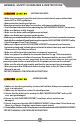
ADJUST HEADLIGHT & TURN SIGNALS
1. Insert the turn signal base through front light bracket. Slide washer and nut to threads and tighten.
Repeat this procedure for front and rear turn signals.
*Once the GAS CHOPPER SCOOTER™ has been assembled and battery has been charged, test the
turn signals to ensure that they are on the correct sides. (Fig. 3)
2. Adjust the headlight and tighten using the provided screwdriver (Fig. 4)
Continued on Next Page
Fig. 4
Fig. 1
Handlebars
Fastening
Knob
Fig. 2
Throttle
Locking
Copper
Button
Fig. 3
Locking Nut
Turn Signal
Adjustment
Screw
Headlight