
Service manual
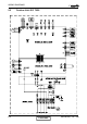
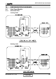
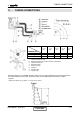
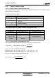
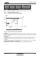
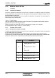
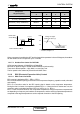
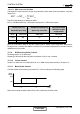
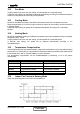
Table Of Contents
- DNG DC Inverter Series
- LIST OF EFFECTIVE PAGES
- TABLE OF CONTENTS
- INTRODUCTION
- PRODUCT DATA SHEET
- RATING CONDITIONS
- OUTLINE DIMENSIONS
- PERFORMANCE DATA & PRESSURE CURVES
- AIRFLOW CURVES
- SOUND LEVEL CHARACTERISTICS
- ELECTRICAL DATA
- WIRING DIAGRAMS
- REFRIGERATION DIAGRAMS
- TUBING CONNECTIONS
- CONTROL SYSTEM
- TROUBLESHOOTING
- EXPLODED VIEWS AND SPARE PARTS LISTS
- APPENDIX A

11-1
TUBING CONNECTIONS
DATA BOOK - DNG DCI
11. TUBING CONNECTIONS
TUBE (Inch)
TORQUE (Nm)
¼” ⅜” ½” ⅝” ¾”
Flare Nuts
15-18 40-45 60-65 70-75 80-85
Valve Cap
13-20 13-20 18-25 18-25 40-50
Service Port Cap
11-13 11-13 11-13 11-13 11-13
1. Valve Protection Cap-end
2. Refrigerant Valve Port (use Allen wrench to open/close)
3. Valve Protection Cap
4. Refrigerant Valve
5. Service Port Cap
6. Flare Nut
7. Unit Back Side
8. Copper Tube
When the outdoor unit is installed above the indoor unit an oil trap is required every 5m along the suction
line at the lowest point of the riser. Incase the indoor unit is installed above the outdoor, no trap is
required.
*Applicable for DNG18 only, for DNG24 – 44 oil traps are not required.
CONTENT