
Service manual
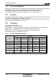
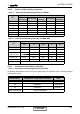
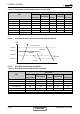
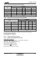
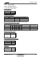
Table Of Contents
- DNG DC Inverter Series
- LIST OF EFFECTIVE PAGES
- TABLE OF CONTENTS
- INTRODUCTION
- PRODUCT DATA SHEET
- RATING CONDITIONS
- OUTLINE DIMENSIONS
- PERFORMANCE DATA & PRESSURE CURVES
- AIRFLOW CURVES
- SOUND LEVEL CHARACTERISTICS
- ELECTRICAL DATA
- WIRING DIAGRAMS
- REFRIGERATION DIAGRAMS
- TUBING CONNECTIONS
- CONTROL SYSTEM
- TROUBLESHOOTING
- EXPLODED VIEWS AND SPARE PARTS LISTS
- APPENDIX A

12-12
CONTROL SYSTEM
SM DNGDCI 2-E.1 GB
OCT – Outdoor Coil Temperature
OAT – Outdoor Air Temperature
TLD – Time from Last Deicing
DI – Deicing Interval (Time Interval Between Two Deicing)
Deicing interval time when compressor is first started in heat mode, is 10 minutes if OCT < -2, and
is 40 minutes in other cases.
Deicing interval time is changed (increased/ decreased in 10 minutes steps) as a function ofdeicing
time. If deicing time is shorter then former deicing time, the deicing interval time will beincreased. If
deicing time is longer then former deicing time, the deicing interval time will bedecreased.
Deicing Operation Procedure
T1=60 secondes;T2=36 secondes;T3=6 secondes
COMP
RV
OFAN
EEV
ON
HEAT
COOL
ON
OFF
EE
VDeicerOpen
Any
T1
12
0
Threshold
DT
max. 12 minutes
OCT
DeiceFreqChRV
CONTENT