
Service manual
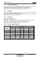
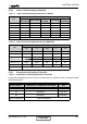
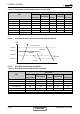
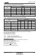
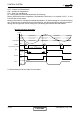
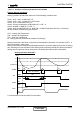
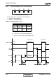
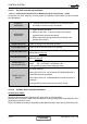
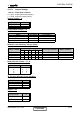
Table Of Contents
- DNG DC Inverter Series
- LIST OF EFFECTIVE PAGES
- TABLE OF CONTENTS
- INTRODUCTION
- PRODUCT DATA SHEET
- RATING CONDITIONS
- OUTLINE DIMENSIONS
- PERFORMANCE DATA & PRESSURE CURVES
- AIRFLOW CURVES
- SOUND LEVEL CHARACTERISTICS
- ELECTRICAL DATA
- WIRING DIAGRAMS
- REFRIGERATION DIAGRAMS
- TUBING CONNECTIONS
- CONTROL SYSTEM
- TROUBLESHOOTING
- EXPLODED VIEWS AND SPARE PARTS LISTS
- APPENDIX A

12-14
CONTROL SYSTEM
SM DNGDCI 2-E.1 GB
12.9.8 Condensate Water Over Flow Protection
Each of the pins P1, P2, P3 can have two options:
1 – When it is shorted with P4
0 – When it is not shorted to P4
Water Level Protection-1 level
P1 P2 P3 Level
Don’t
care
Don’t
care
1 Normal
Don’t
care
Don’t
care
0 Overflow
(*) 1- Pin P1, P2, or P3 is connected to P4.
0- Pin P1, P2 or P3 is not connected to P4.
ANY
0
ON
NLOAD
PUMP
OFF
ON
OPER
LED
OFF
Overflow
Water Level
Normal
BLINK
NLOAD is
forced to 0
8 min 8 min
Overflow when
unit is ON
Overflow when
unit is OFF
8 min
P1 P2 P3 P4
Level Connector Top View
CONTENT