USER AND INSTALLATION MANUAL WHITE iQool9 iQool12 iQool18 iQool24 BLACK iQool9B iQool12B iQool18B iQool24B 9,000 BTU 12,000 BTU 18,000 BTU 24,000 BTU SMART WIFI CONTROLLED WALL MOUNTED INVERTER SPLIT AIR CONDITIONER WITH HEAT PUMP Thank you for choosing an electriQ Air Conditioner Please read this user manual before using this innovative Air Conditioner and keep it safe for future reference.
SAFETY INSTRUCTIONS SAFETY INSTRUCTIONS 3 OPERATION INDOOR UNIT OUTDOOR UNIT REMOTE CONTROL SETTING UP THE REMOTE DISPLAY PANEL FUNCTIONS 5 6 6 7 8 8 9 WIFI CONTROL BEFORE YOU START DOWNLOAD THE APP TO YOUR PHONE ACTIVATING THE APP REGISTER THE APP EMAIL REGISTRATION SMS REGISTRATION FORGOTTEN PASSWORD CONNECTION METHODS AVAILABLE FOR SETUP CHANGING BETWEEN CONNECTION TYPES ADDING A DEVICE CONNECTING USING CF MODE (QUICK CONNECTION) CONNECTING USING AP MODE (ALTERNATIVE METHOD) USING THE TIMER FUNCTION
SAFETY INSTRUCTIONS IMPORTANT! • Carefully read the instructions before operating the unit • This appliance comprises of an indoor and an outdoor unit. The indoor slim evaporator is designed exclusively for indoor installations while the external condenser can be installed outside while still away from flood water or snow line. • Always place the unit on a dry and stable surface.
SAFETY INSTRUCTIONS • • • • • • immersing it in water. Any service other than regular cleaning or filter replacement should be performed by an authorized service representative or a qualified air conditioning engineer. Failure to comply could result in a voided warranty. This air conditioner is intended for cooling / heating a room to a suitable level for human comfort, and should not be used for any other purpose such as cooling food.
OPERATION COOLING MODE 2 1 3 4 5 7 8 6 The compressor (6) in the external unit compresses the refrigerant into a high-temperature, highpressure gas. When this gas flows along the cooling fins of the condenser (7), heat is exuded and the gas condenses into a liquid, which is then led to the evaporator (1) in the indoor unit. The liquid expands into a gas at a low temperature and low pressure.
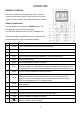
OPERATION INDOOR UNIT No. 1 2 3 4 5 6 7 8 9 10 11 Description Front panel Air filter Optional filter LED Display Signal receiver Terminal block cover Ionizer generator (not applicable on all models) Deflectors Emergency button Indoor unit rating label Airflow direction louver OUTDOOR UNIT No.
OPERATION REMOTE CONTROL The remote control has a range of up to 8m. Point the remote control at the receiver in the interior unit. A beep confirms that the remote control signal has been received. REMOTE OPERATION Turn the appliance on using the ON/OFF button. This activates the most recently used setting. The ON/OFF button also turns the air conditioner off. *Horizontal swing not available on most models and the horizontal direction must be adjusted manually. No.
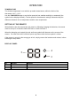
OPERATION TEMPERATURE The desired temperature is set with the up and/or down button, within the limits of the thermostat: 16°C – 31°C. Use the FAN SPEED button to set the fan speed at low, medium and high; or automatic (the symbol on the display will flash). The fan speed in the automatic setting is determined by the difference between the set temperature and the room temperature.
OPERATION FUNCTIONS COOL 1. Press the MODE button until the COOL indicator appears. 2. Set the desired temperature. 3. Use the FAN button to set the fan speed. HEAT 1. Press the MODE button until the HEAT indicator appears 2. Set the desired temperature. 3. Use the FAN button to set the fan speed. FAN MODE 1. Press MODE button until the FAN indicator appears. 2. The temperature settings are disabled in fan mode. 3. Use the FAN button to set the fan speed, cycling through LOW / MED / HIGH / AUTO.
OPERATION SLEEP MODE 1. Press the SLEEP button 2. Set the desired temperature. 3. Press the SLEEP button; The SLEEP indicator will appear on the display. Cancel the sleep mode by pressing the button again. 4. The fan will operate at low speed. 5. The temperature is automatically altered by 1 oC every hour for 2 hours. In cooling mode the temperature will rise, in heating it will fall. 6. After 10 hours in Sleep mode the unit will power off automatically. TURBO 1.
OPERATION IMPORTANT INFORMATION HEATING MODE When the air conditioner is placed in heating mode, the indoor unit will appear to be inactive while it follows it’s preheat procedure to heat the evaporator coils. Once the coils have heated, the indoor fan will start to run. This process usually takes 1 – 3 minutes, and is designed to ensure that cold air is not circulated. AUTO RESTART The air conditioner will automatically restart when electricity is restored after a power cut.
WIFI CONTROL BEFORE YOU START • • • Ensure your router provides a standard 2.4ghz connection. If your router is dual band ensure that both networks have different network names (SSID). The provider of your router / ISP will be able to provide advice specific to your router. Once the app has been installed on your phone, turn off the data connection, and ensure your phone is connected to your router via WiFi.
WIFI CONTROL ACTIVATING THE APP The first time the app is used, it will need activating. To do this, either press the scan button, and scan the QR code below, or press “Enter Activation Code” and enter the activation code: electriQ REGISTER THE APP Upon the first use, an account will need to be registered. Click on the “Register” button to enter the registration screen.
WIFI CONTROL SMS REGISTRATION Press on the option at the bottom of the screen to choose the option for registering with a mobile number. You will receive an activation code via SMS. Enter the activation code into the verification code box, before entering your new password in the box below. Please note the password should be at least 6 characters and include letters and numbers. Then press the confirm button to log in.
WIFI CONTROL CONNECTION METHODS AVAILABLE FOR SETUP The air conditioner has two different setup modes, CF (Quick Connection) and AP (Access Point). The CF mode is a quick and simple way to set the unit up. The AP connection uses a direct local WiFi connection between your phone and the air conditioner to upload the network details.
WIFI CONTROL CONNECTING USING CF MODE (QUICK CONNECTION) 1. Ensure that the display on the air conditioner is displaying CF before pressing “Next Step” (otherwise to change the connection mode: Quickly press the display button on the remote 6 times and wait 10 seconds until CF is displayed) 2. Select your WiFi router from the drop down list and enter the password (Please note the password is case sensitive) before pressing next.
WIFI CONTROL CONNECTING USING AP MODE (ALTERNATIVE METHOD) 1. Ensure that the screen on the air conditioner is displaying AP (otherwise to change the connection mode: Quickly press the display button on the remote 6 times and wait 10 seconds until AP is displayed) 2. Press on the AP Mode button in the top right of the screen to change the app to AP mode connection. 3. Select your WiFi router from the drop down list and enter the password (Please note the password is case sensitive) before pressing next. 4.
WIFI CONTROL The app will automatically upload the connection information to the air conditioner, once the connection is completed, a message will be displayed to confirm. On this page there is the option to rename the air conditioner to something more relevant. If the connection fails, please retry the connection, failing this try connecting using the CF mode connection.
WIFI CONTROL CONTROLLING YOUR DEVICE THROUGH THE APP Now that your air conditioner is linked up to your network, you can control it from your phone. Select your device in the device list to gain access to the controls for the device. Use the + and – buttons to increase and decrease the desired temperature. The tabs on the bottom of the screen should be used to change other settings. Mode: Allows the operating mode to be changed between Feel, Heat, Dry, Cool and Fan.
WIFI CONTROL USING THE TIMER FUNCTION The timer can be used to either set a time for the air conditioner to turn on (and specify the settings it will run with), or a time for the unit to turn off. Multiple timers can be used together to build a schedule with on and off times. 1. Press the Timer button at the bottom right of the screen. 2. To set a new timer, press the “Add Timer” button at the bottom of the screen.
WIFI CONTROL MORE SETTINGS When on the main screen the three dots in the top right hand corner give you access to the settings options for the app. This a number of extra options for modifying the name of the air conditioner, and removing a device from the app.
MAINTENANCE FILTERS Ensure the power is turned off to the unit before attempting to service the filters. OPENING THE FRONT PANEL: At the recesses, pull the front part up with both hands. The front panel will stay horizontal (at around 90°). CLOSING THE FRONT PANEL: Press the front part down at the sides and in the middle. Make sure it is properly clicks into place. REMOVING AND REPLACING THE FILTERS 1. Hold the front panel open (or put it in horizontal position) and remove the filter(s). 2.
MAINTENANCE END OF SEASON If the air conditioner is not going to be used for an extended period: • • • • Set in fan mode on a slightly warm day so that the inside of the appliance dries out. Switch off the power at the fuse box and remove the batteries from the remote control. Clean the filters. Remove the batteries from the remote control.
INSTALLATION GUIDE SAFETY • Only qualified personnel should install this appliance. This installation manual is intended for use by individuals possessing adequate backgrounds and qualifications in electrical, electronic, refrigerant and mechanical fields. Any attempt to install or repair the appliance may result in personal injury and property damage. • The manufacturer and retailer cannot be responsible for the interpretation of this information, nor can it assume any liability in connection with its use.
INSTALLATION GUIDE INDOOR UNIT POSITION The air inlet and outlet vent should be away from any obstruction, ensuring that there is a good airflow through the whole air-conditioned space. Select a position where the condensing water can be easily drained out, and the indoor unit can be easily connected to outdoor unit. The wall where the unit is fixed should be strong enough to withstand the full weight and vibration of the unit. The unit should be accessible for service and maintenance.
INSTALLATION GUIDE RECOMMENDED INSTALLATION SPACING DIAGRAM 26
INSTALLATION GUIDE TOOLS RECOMMENDED FOR INSTALLATION Electric Drill Hammer Screwdrivers Tape Measure Core Hole Cutter Spirit Level Number 14 (7mm) Masonry Drill Pencil and Chalk 1.
INSTALLATION GUIDE 1. Check the area for any hidden wires or pipes. 2. Mark the right hand backplate screw position. 4. Tap a 7mm wall plug into position. 5. Screw the backplate to the wall using 1.5 inch number 10 screws. 3. Remove the backplate and drill a 7mm hole. 6. Check to ensure level, then mark the other holes and swing the backplate away. 7. Drill the rest of the holes and insert the wall plugs. 8. Fix the backplate to the wall. 9.
INSTALLATION GUIDE INFORMATION REGARDING THE INSTALLATION OF THE INDOOR UNIT INSTALLING THE REAR PANEL 1. Always mount the rear panel horizontally. Due to the water tray within the indoor unit we would advise that the outlet of the water tray should be fractionally lower when installing as this will aid drainage of the condensate collected. 2. Fix the rear panel on the wall with screws. 3.
INSTALLATION GUIDE Notes: 1. The height of the installed unit is recommended to be > 200 cm. 2. Either the indoor unit or the outdoor unit can be higher, but the height difference must comply with a max. 5 metres level difference. 3. Try to avoid bending the pipes as much as possible so as to avoid possible negative impacts upon the performances of the unit.
INSTALLATION GUIDE STANDARD PIPELINES CONNECTION & AIR PURGING No dust or any other particles, air or moisture should be allowed to enter the air conditioning system. Careful attention should be paid when pipeline connection for outdoor unit is made. Try to avoid repeated curves as much as possible; otherwise damage to the copper pipes may occur. Suitable wrenches should be used when the pipeline connection is done so as to ensure appropriate torque (refer to following torque table).
INSTALLATION GUIDE ADDING REFRIGERANT Refrigerant must be added if the pipe length is more than 5 metres (16'5"). This operation can only be performed by a professional F-Gas engineer, for the additional gas amount, see the below Liquid pipe diameter Φ6.3 or Φ6 (1/4) Φ9.
INSTALLATION GUIDE NOTES: The copper pipe used in the refrigeration lines are very soft, high pressure copper and prone to get damaged if not handled correctly. Try to avoid bending or stretching the pipework. Always ensure the pipes are protected when running through the wall to help prevent damage to the pipes. To keep the allowed bending radius please make the packed soft pipes vertical before extending Please do not extend only one side of the packed soft pipes.
INSTALLATION GUIDE ELECTRICAL CONNECTION OF THE AIR CONDITIONER • The electrical connections can be found under the protective plastic cover. Remove this from the side of the outdoor unit to gain access to the electrical connections. • Connect the indoor power and control wires with the matching outdoor wire as per the electrical diagram. • Do not attempt to connect the wires in a different way to the diagram on the air conditioner as this could damage the unit and invalidate the warranty.
ELECTRICAL WIRING DIAGRAMS Please note: The diagrams provided in the manual are for guidance only.
ELECTRICAL WIRING DIAGRAMS iQool24(B) 36
TROUBLESHOOTING AND SELF DIAGNOSIS MALFUNCTION The appliance does not operate POSSIBLE CAUSE Power failure Damaged indoor/outdoor unit fan motor Faulty compressor thermomagnetic circuit breaker Faulty protective device or fuses Loose connections Self protection in adverse conditions Voltage higher / lower than the voltage range Active TIMER-ON function Damaged electronic control board Strange odour Air filter dirty Noise of running Back flow of liquid in the refrigerant circulation water A fine mist This o
TROUBLESHOOTING AND SELF DIAGNOSIS ERROR SIGNALS ON THE DISPLAY In case of error, the display on the indoor unit shown the following error codes: Error Light flash code Failure type Code E0 Run & Timer – both blinking Indoor and outdoor communication failure EC Run & Timer – both blinking Outdoor communication failure E1 Run – 1 flash every 8 seconds Indoor room temperature sensor E2 Run – 2 flashes every 8 seconds Indoor coil temperature sensor E3 Run – 3 flashes every 8 seconds Outdoor coil temperature se
TROUBLESHOOTING AND SELF DIAGNOSIS OUTDOOR UNIT FAULT CODES The outdoor unit has an LED on the power board. This LED will be illuminated when the compressor is running and blink 1s on and 1s off when the compressor is in standby. If there is a fault on the outdoor unit, it will blink on and off for half a second at a time, followed by a 3s gap. The number of consecutive blinks will show the fault as per the table below: No.
TROUBLESHOOTING AND SELF DIAGNOSIS Description Possible Cause 1. Check the mobile device is connected to WiFi 2. Check the AC is connected Air conditioner 3. Check that any firewall or other restrictions are causing can’t be configured problems successfully 4. Check the router is functioning normally 5. Check that the router isn’t blocking the App The app displays “Identification failed”. This indicates that the AC Mobile device can’t has been reset and the mobile device has lost contact with the AC.
TECHNICAL SPECIFICATION Model iQool9 – V4 iQool12 – V4 iQool18 – V4 iQool24 – V4 iQool9B iQool12B iQool18B iQool24B Rated voltage and frequency 1Ph/220-240V~/50Hz 1Ph/220-240V~/50Hz 1Ph/220-240V~/50Hz 1Ph/220-240V~/50Hz 13A 13A 13A 16A (Ph-V-Hz) Fuse Required Mode Cooling Heating Cooling Heating Cooling Heating Cooling Heating Rated capacity (W) 2600 2610 3400 3420 5130 5230 6810 6870 (940~ (940~ (1000~ (1000~ (1250~ (1350~ (1830~ (1850~79 3320) 3380) 3770) 381
TECHNICAL SPECIFICATION Packaging (W*D*H) 838 x 338 x 540 838 x 338 x 540 890 x 385 x 628 960 x 430 x 732 24 / 27 24 / 27 34 / 37 40 / 45 50 50 55 57 60 60 65 67 R32/530g R32/550g R32/920g R32/1060g (mm) Net / Gross Weight (Kg) Noise – Sound pressure level (dB/A) Noise – Sound power level (dB/A) Refrigerant type/weight Defrost mode Automatic defrosting Automatic defrosting Automatic defrosting Automatic defrosting Applicable climate Cooling (0 C – 53 C) Cooling (0 C – 53 C) Cool
SUPPORT WARRANTY INFORMATION electriQ guarantee provides cover against material or manufacturing faults. This means that if your air conditioner develops a fault during the guarantee period, we will arrange for it to be repaired or replaced. Faults arising from a faulty installation are specifically excluded. The system must be serviced annually by qualified personnel. This unit must be operated under conditions as recommended in this user manual, at voltages indicated on the unit.