32-33 47th Avenue Long Island City, New York 11101 ph: 718 937 8300 fx: 718 937 9111 www.ehx.com User Reference Manual Manual Notice: This manual is provided as both a guide for instruction, as well as a reference to be kept near by to aid you in everyday use. In it you will find general information, regarding the Bi-Filter as well as instructions for real and suggested operating procedures, setup and use. This manual is subject to change without notice.
Thank you for purchasing the ElectroHarmonix Bi-Filter. Please read this manual–written to be a reference guide that you can keep close by–in order to familiarize yourself with this unique instrument’s layout. The BiFilter’s sound is wonderful and can truly set your music apart, but the key is your creativity. TABLE OF CONTENTS Copyright 2003 Electro-Harmonix. All rights reserved. Bi-Filter and Electro-Harmonix and logo are trademarks of New Sensor/Electro-Harmonix.
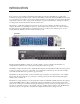
INTRODUCTION In the complex world of modulation instruments, Electro-Harmonix introduces the Bi-Filter. It’s a totally analog instrument, drawing upon the filter designs of the past while utilizing a front panel that brings EVERY relevant control, for every parameter, to the surface. You are given complete interactive access.
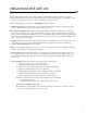
PRECAUTIONS FOR SAFE USE Please read the manual carefully, as it was written to help you understand the operation capabilities of your new instrument. Carefully review the safety precautions as they ensure a long and trouble free life for your Bi-Filter, as well as your own safety. Keep your manual in an easily accessible place for future reference. The following instructions, on this page, are WARNINGS that must be followed. 1.
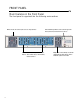
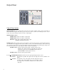
FRONT PANEL Main Features in the Front Panel The front panel is organized into the following main sections: Drivers: Provide the control signal sources to sweep the filters Filter 1: State-variable voltage controlled filter Filter 2: State-variable voltage controlled filter, identical to Filter 1 5 Filter and FX Loop switches: Panel control to bypass the filters (entire unit) and external FX loop effects Output Mixer: Allows mixing of both filter outputs with the input signal as well as switchable opti
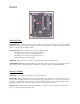
Drivers Envelope Drive ENV DRIVE Slider: Controls the envelope follower sensitivity to the input signal. Generally set it so the red OVER LED blinks on the loudest notes, but all settings produce interesting effects. This is not an all or nothing fader. Different locations on the slider produce different results. LOG/LIN Switch: Provides different dynamic response to the input signal. • The LOG position produces consistent envelope tracking no matter how soft or aggressive your input signal is.
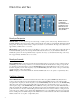
Filters One and Two NOTE: FILTER 1 and FILTER 2 HAVE IDENTICAL CONTROLS AND RESPONSE, BUT ARE SEPARATELY ADJUSTABLE. Envelope Response ATTACK Slider: Controls the time response of the rising or "attack" portion of the envelope. When the slider is in the FAST (DOWN) position, the envelope will rise with nearly the same attack as your instrument. When in the SLOW (UP) position, the envelope will rise slowly compared to the attack of your instrument.
Filters One and Two (Continued) Filter, Frequency and Range Controls FILTER FREQ Slider: Sets the filter frequency within its operating range. When no envelope or LFO signals are present, the frequency of the filter is set by the position of this slider. To perform a manual filter sweep, simply push this slider up or down. RANGE Switch: Changes the sweep range of the filter: LOW position gives the filter a sweep range from 150 Hz to 5 kHz. HI position gives the filter a sweep range from 350 Hz to 12 kHz .
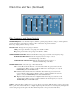
Output Mixer Output Mixer Section OUTPUT MIXER: Provides a 3 channel audio mixer where the signals from Filter 1, Filter 2 and the original Dry signal can all be mixed together. These sliders give the user precise control over their sound, enabling the user to “season to taste” the amount of filtering versus the amount of original signal. OUTPUT LEVEL Controls: FILTER 1 Slider: Mixes in the Filter 1 output signal. FILTER 2 Slider: Mixes in the Filter 2 output signal.
Bypass Section FILTERS Switch and LED: Puts the entire Bi-Filter into TRUE BYPASS MODE or EFFECT MODE. When the switch is in the DOWN position, the FILTERS LED, above it, will be off and the entire unit is in true bypass mode. In true bypass mode, the signal into the AUDIO INPUT Jack is connected directly to the MAIN OUTPUT Jack and disconnected from the Bi-Filter circuit. When the switch is in the UP position, the FILTERS LED will be on and the unit is in effect mode.
REAR PANEL 12 11 11 10 9 8 7 6 5 4 3 2 1 1. AUDIO INPUT: Main audio input into the Bi-Filter. Signals from a mixing board or a musical instrument go here. 2. EFFECTS SEND: EFFECTS SEND is an Output jack that provides a buffered, preamplified version of the signal present at the AUDIO INPUT jack. This signal can be used to go into an external effects loop. The output present at this jack is after the AUDIO BOOST switch on the front panel. 3.
REAR PANEL (Continued) 12 11 10 9 8 7 6 5 4 3 2 1 7. ENVELOPE 1 CV OUTPUT: This jack Outputs a Control Voltage of Envelope Follower 1 which modifies Filter 1. The range of this output is 0 - 14 Volts DC. 8. ENVELOPE 2 CV OUTPUT: This jack Outputs a Control Voltage of Envelope Follower 2 which modifies Filter 2. The range of this output is 0 - 14 Volts DC. 9. FILTER 1 CV INPUT: Accepts a DC Control Voltage that controls the sweep of Filter 1 through its entire range.
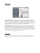
BLOCK DIAGRAM: AUDIO AND CONTROL SIGNAL PATHS Effects Send Output Unit Bypass Relay Audio Input Unit Bypass Relay Audio Boost SW Filter 1 Invert SW FX Loop Bypass Relay down down Filters Bypass SW Range FX Loop Bypass SW Mode To ENV Circuit Q Slider Filter 1 CV Effects Return Input Filter 1 Mixer Slider X1-X51 ENV Drive Slider Filters Bypass SW Inverter Bypass Footswitch TIP BUF Main Output FILTER 1 up up Bypass Footswitch TIP Dry Mixer Slider Filter 1 Output Filter 2 Invert SW
SPECIFICATIONS • Maximum Input Signal Level: 6.3 VRMS (+18 dBV) • Maximum Control Voltage Input Level: 5 VDC. • Minimum Control Voltage Input Level: 0 VDC. • Maximum Signal Gain (Q Control = 10): 34 dB • Minimum Signal Gain (Q Control = 1): 0 dB • Sensitivity for Full Envelope Sweep: (ENV Drive Control = 1): 1.
SAMPLE SETTINGS Try this setting first with a funky rhythm! Slow Dual Envelope Sweep: Smooth slow envelope up sweep with two filters Highpass Dual Down Drive: Chunky sweep, which is good for heavily accented lines and adds percussiveness to your attack. Try out different settings of the Filter RANGE, MODE, INVERT, and MIX controls. Gated Envelope Sweep: Both the LFO and Envelope are acting on the Filters to produce a setting that sounds as if the envelope is being gated by the LFO.
SAMPLE SETTINGS (Continued) LFO Phase Sweep: The internal LFO's sweep the filters and sound a bit like—but different than—a phasor. Envelope and Oscillator: Sweep one filter with the Envelope and the other filter with a fast LFO, for a dynamic AND rhythmic filter effect. Pop-Tone: A very dramatic effect, especially useful on staccato solos and rhythms, for guitar and bass. Sci-Fi Sweep: The LFO is acting on the Filters with a falling sawtooth waveform.
BLANK PROGRAM SHEET Please photocopy for your own reference.