
User Guide
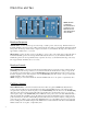
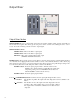

Bypass Section
FILTERS Switch and LED: Puts the entire Bi-Filter into TRUE BYPASS MODE or EFFECT MODE. When the
switch is in the DOWN position, the FILTERS LED, above it, will be off and the entire unit is in true bypass mode. In
true bypass mode, the signal into the AUDIO INPUT Jack is connected directly to the MAIN OUTPUT Jack and dis-
connected from the Bi-Filter circuit. When the switch is in the UP position, the FILTERS LED will be on and the unit is
in effect mode. In effect mode, the signal into the AUDIO INPUT Jack is connected to the Bi-Filter circuit. The output
of the OUTPUT MIXER section of the Bi-Filter is then connected to the MAIN OUTPUT Jack.
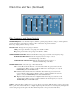
FX LOOP Switch and LED: Switches the effects send and return loop on or off. When the switch is in the DOWN
position, the FX LOOP LED will be off and the external effects loop that is connected to the EFFECTS SEND and
EFFECTS RETURN jacks will bypassed. When the switch is in the UP position, the FX LOOP LED will be on and the
external effects loop connected to the EFFECTS SEND and EFFECTS RETURN jacks will be engaged. When FX
LOOP is on, the external effects loop will be part of the Bi-Filter circuitry. Special Note: When nothing is plugged into
the EFFECTS RETURN jack, the FX LOOP Switch will have no function. This switch will only appear to be working
when a cable is plugged into the EFFECTS RETURN jack of the Bi-Filter.
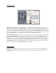
Power Switch
POWER Switch and LED: Controls the AC power to the entire unit. The BLUE LED above the POWER Switch
indicates the Bi-Filter is ON. The unit is ON when the switch is in the up position, OFF when the switch is in the
down position.