
User Guide
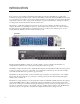
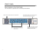
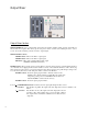

Filters One and Two
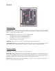
Envelope Response
ATTACK Slider: Controls the time response of the rising or "attack" portion of the envelope. When the slider is in
the FAST (DOWN) position, the envelope will rise with nearly the same attack as your instrument. When in the SLOW
(UP) position, the envelope will rise slowly compared to the attack of your instrument. The range of the attack time is
approximately 5 milliseconds to 1.5 seconds.
DECAY Slider: Controls the time response of the falling or "decay" portion of the signal envelope. When the slider is
in the FAST (DOWN) position, the envelope will fall with nearly the same decay as your instrument. When in the
SLOW (UP) position, the envelope will fall slowly compared to the decay of your instrument. The range of the decay
time is approximately 10 milliseconds to 1.5 seconds.
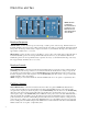
Envelope Amount
ENV AMOUNT Slider: Controls the amount and direction that the filter is swept by the envelope follower. In the 0
(CENTER) position, the envelope follower does not affect the filter. In the UP direction, the envelope sweeps the fil-
ter’s frequency up from the frequency set by the FILTER FREQ slider. In the DOWN direction, the envelope sweeps
the filter’s frequency down from the frequency set by the FILTER FREQ slider. The amount of sweep is continuously
variable depending on the control settings.
NOTE: sweeping one of the filters UP and the other filter DOWN results in an “out of phase” complementary drive.
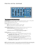
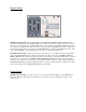
Oscillator Amount
OSC AMOUNT Slider: Controls the amount and direction of filter sweep by the SWEEP OSC (LFO). In the 0
(center) position, the LFO does not affect the filter. For both the UP and DOWN directions of the slider, the LFO
sweeps the filter’s frequency around the frequency set by the FILTER FREQ slider. In other words, the FILTER FREQ
slider will set the center frequency and the LFO will sweep the filter above and below that center. So to sweep the
entire frequency range, set the FILTER FREQ slider to MED (the center position) and set the OSC AMOUNT slider to
either the maximum UP or DOWN positions. The difference between the UP and DOWN positions is that in the UP
position the LFO is non-inverted, in the DOWN position the LFO waveform is inverted. If there is a rising sawtooth
set up in the sweep oscillator section, and the OSC AMOUNT slider is set to the DOWN position, the waveform will
become a falling sawtooth. NOTE: Setting the OSC AMOUNT of one filter UP and the other filter’s OSC AMOUNT
DOWN, results in an "out of phase" complementary drive.
NOTE: FILTER 1
and FILTER 2
HAVE IDENTICAL
CONTROLS AND
RESPONSE, BUT
ARE SEPARATELY
ADJUSTABLE.
7