
User Guide

Filters One and Two (Continued)
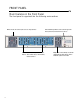
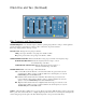
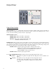
Filter, Frequency and Range Controls
FILTER FREQ Slider: Sets the filter frequency within its operating range. When no envelope or LFO signals are
present, the frequency of the filter is set by the position of this slider. To perform a manual
filter sweep, simply push this slider up or down.
RANGE Switch: Changes the sweep range of the filter:
LOW position gives the filter a sweep range from 150 Hz to 5 kHz.
HI position gives the filter a sweep range from 350 Hz to 12 kHz .
OVER/UNDER RANGE LEDs: Indicates that the filter is being swept to its limits of the frequency range.
OVER RANGE RED LED: Indicates the frequency has been swept to or above
the maximum range of the filter.
UNDER RANGE YELLOW LED: Indicates the frequency has been swept to or
below the minimum range of the filter.
FILTER MODE Switch: Selects the type of filter characteristic:
LP: Low Pass Mode turns the filter into a Low Pass filter which only passes audio below the
cutoff frequency. With no envelope or LFO modulation, the cutoff frequency is set by the
FILTER FREQ slider and RANGE switch.
BP: Band Pass Mode turns the filter into a Band Pass filter which only passes audio in the
region around the center frequency. With no envelope or LFO modulation, the center fre-
quency is set by the FILTER FREQ slider and the RANGE switch.
HP: High Pass Mode turns the filter into a High Pass filter which only passes audio above the
cutoff frequency. With no envelope or LFO modulation, the cutoff frequency is set by the
FILTER FREQ slider and RANGE switch.
Q Slider: Adjusts the filter’s quality factor or “Q”, also known as resonance. With this slider you have control of the
filter’s “peak” from a flat roll-off curve to a highly emphasized peak at the cutoff or center frequency. The higher the
control setting, the greater the peak of the filter, which will produce a more pronounced filter effect.