PITCH FORK®+ POLYPHONIC PITCH-SHIFTER/HARMONY PEDAL Congratulations on your purchase of the Electro-Harmonix PITCH FORK®+, a fully featured polyphonic pitch-shifter/harmony pedal. The PITCH FORK®+ has two independent pitch shifting engines each capable of transposing over a +/- 3 octave range and detuning +/- 99 cents. Both shift voices have their own volume control and a third for a dedicated DRY level control. There are two output jacks MAIN and AUX. The AUX output offers multiple routing options.
QUICK START GUIDE Plugging in the PITCH FORK®+ 1. Connect the EHX9.6DC Power Adapter into the 9V jack at the top of the pedal. Plug the AC Adapter into an AC outlet. 2. Connect your guitar or other instrument to the INPUT jack using a standard 1/4” instrument cable. Connect the MAIN OUTPUT jack to your amp with another standard 1/4” instrument cable. 3. If using AUX, also connect the AUX OUTPUT jack to an additional amp using another standard 1/4” instrument cable. 4.
CONNECTIONS INPUT Jack – Audio input with an impedance of 2.2MΩ. MAIN OUTPUT Jack – Main audio output with an impedance of 470Ω. AUX OUTPUT Jack – Auxiliary audio output with an impedance of 470Ω. EXP Jack – Expression pedal or control voltage (CV) input. The PITCH FORK®+ allows for an expression pedal to be assigned to a number of different parameters. See EXP Mode section for more details. Expression input jack accepts a TRS expression pedal connector or a TipSleeve 0-5V control voltage input.
CONTROLS & DISPLAY DRY Knob – Controls the volume level of the DRY signal. SHIFT 1 Knob – Controls the effect volume level of SHIFT 1. SHIFT 2 Knob – Controls the effect volume level of SHIFT 2. VALUE Knob – VALUE is a rotary encoder that can rotate continuously in either direction, and be pushed like a button. VALUE will adjust the selected mode parameter, enter sub-menus, or save presets to memory. A press of VALUE enters sub-menus when applicable. Holding VALUE when in PRESET mode saves a preset.
OVERVIEW OF MODES The PITCH FORK®+ has eight control modes that are accessed by pressing one of the eight illuminated buttons. The mode buttons can be used to exit, go back to previous sub-menus, or back to the main mode menu. Selecting a different mode button resets the previously selected mode to its main menu and brings you to the newly pressed mode. AUX – AUX mode selects which channel is sent to the AUX output jack.
MODE BUTTON FUNCTIONS Each Mode button allows for control over its corresponding parameters. When a Mode button is pressed, it will illuminate, and display its current selection. You can then use the VALUE knob to scroll values, enter a submenu, or save and load presets. AUX Mode – In AUX mode, the VALUE knob is used to select the channels that are sent to the AUX output. The selected channels will not be sent to the MAIN output with the exception of “ALL.
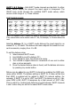
SHIFT 1 & 2 Modes – Both SHIFT mode channels are identical. In either mode, VALUE selects the amount the input signal is transposed. The VALUE knob scrolls through the available SHIFT mode values, which covers a total range of +/- three octaves. SHIFT MODE VALUES D.
EXP Mode – The EXP mode menu assigns the expression pedal/control voltage (CV) signal within each of the three available sub-menus. Use the VALUE knob to scroll between the FREQ, GLIS, and VOL sub-menus. Press VALUE to enter the selected sub-menu. ▪ FREQ. – Expression/CV controls the Frequency of the selected SHIFT • • • • • channel creating whammy bar pitch bend effects.
USER Mode – The user programmable footswitch can be assigned to control different parameters or augment certain features. For BLND, 1XF2, 1X2D, D1X2 and 1XS2, holding down the footswitch will behave like a pseudo expression pedal. The crossfade rate for these modes is set within the RISE and FALL sub-menus under MOME in LATCH mode. When using one of these five USER modes, the BYPASS footswitch changes to LATCH mode, even if MOME is currently selected.
With the USER mode button is set to JUMP, any number of presets can be chained together. To set up a JUMP preset chain: 1. Press the PRESET button and use the VALUE knob to select the preset that will start the preset chain. 2. Press the USER mode button and use VALUE to select JUMP. 3. Press VALUE to enter the JUMP sub-menu. 4. Turn VALUE to select the preset that the USER footswitch will jump to and load. 5. Press PRESET, then press and hold VALUE for 2 seconds to save the preset.
PRESET MODE – In PRESET mode, the VALUE knob selects which presets to load, and save. Turn VALUE to select a desired preset then press VALUE to load the selected preset. The PITCH FORK®+ comes loaded with 10 unique factory presets (see page 12) and 90 empty slots. The factory presets will guide you through the pedal’s potential by showcasing some of its features. Any of these factory presets can be overwritten at any time. See page 12 for instructions on how to restore the factory presets.
RESTORING FACTORY PRESETS: PRESET SLOTS 1-10 1. Power up the PITCH FORK®+ with the PRESET mode button held DOWN. 2. The display will read, “FACTORY PRESETS RESTORED” before normal startup. 3. The presets for slots 1-10 are now restored to the original factory settings.
LATCH MODE – Latch mode selects how the BYPASS footswitch operates. It can be set to either latching or momentary with glissando (glide) effect control. ▪ ▪ LATC – Latching mode toggles the effect ON/OFF with each press of the BYPASS footswitch. MOME. – Momentary mode engages the glissando effect when the BYPASS footswitch is pressed. The speed of glissando’s rise and fall times and the SHIFT channels affected are set in the following sub-menus. Press VALUE to enter momentary mode’s main menu: • RISE.
EXT FOOTSWITCH FUNCTIONS The EXT input jack on the PITCH FORK®+ provides expanded control with an external foot controller, such as the EHX Triple Foot Controller or Digitech® FS3X. Using a TRS cable, connect the foot controller to the EXT input. Now use the external foot controller to change modes, enter/exit sub-menus, load presets, and scroll through parameter values. The foot controller has three footswitches, Mode (Tip), Up (Ring) and Down (Tip+Ring).
COMPLIANCE Note: This equipment has been tested and found to comply with the limits for a Class B digital device, pursuant to part 15 of the FCC Rules. These limits are designed to provide reasonable protection against harmful interference in a residential installation. This equipment generates, uses and can radiate radio frequency energy and, if not installed and used in accordance with the instructions, may cause harmful interference to radio communications.
WARRANTY INFORMATION Please register online at http://www.ehx.com/product-registration or complete and return the enclosed warranty card within 10 days of purchase. Electro-Harmonix will repair or replace, at its discretion, a product that fails to operate due to defects in materials or workmanship for a period of one year from date of purchase. This applies only to original purchasers who have bought their product from an authorized Electro-Harmonix retailer.