ELECTRO-BOILER Commercial Series INSTALLATION & OPERATING INSTRUCTIONS Model APPLICATION: EB-CX Series This Electro-Boiler is factory equipped with WarmFlo smart controller. WarmFlo automatically regulates outlet water temperature at the temperature level set on the front panel. This is a dial switch having eight positions. Setting of this dial is dependent upon the setup configuration of the controller included with the Electro-Boiler being installed.
TABLE OF CONTENTS Description Page Table 1, Specific Model Number, Specific Information 1 Introduction 2 System or Water Flow 3 Multiple Zones & Radiant Temperatures 3 Zone Controller 3 Room Thermostat Placement 4 Multiple Boilers 4 Two-Temperature Operation or Feature 4 Installation Requirements 6 Mechanical Installation Under-Floor Radiant 8 Dual Heat 9 Electrical Hookup 10 Water Fill Procedure 11 Controller Setup 12 Operational Tips 14 Replacement Parts List 16 Troublesh
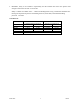
Table 1 – Specific Model Number, Specification Information Stages – kW Model EB-CX-18-60 EB-CX-24-60 EB-CX-30-60 EB-CX-36-60 EB-CX-45-60 EB-CX-54-60 EB-CX-18-48 EB-CX-36-48 EB-CX-54-48 EB-CX-27-20 EB-CX-40-20 EB- CX-27-24 EB-CX-40-24 EB-CX-31 EB-CX-36 EB-CX-40 EB-CX-44 Voltage Rating 600V 3-phase 600V 3-phase 600V 3-phase 600V 3-phase 600V 3-phase 600V 3-phase 480V 3-phase 480V 3-phase 480V 3-phase 208V 3-phase 208V 3-phase 240V 3-phase 240V 3-phase 240V Single phase 240V Single phase 240V Single phase 240
INTRODUCTION With this WarmFlo configuration, the electric heating elements are automatically controlled to establish a fixed outlet water temperature. This outlet temperature is sensed by the WarmFlo controller and is controlled to achieve and maintain the boiler’s set point temperature.
SYSTEM OR WATER FLOW In order to prevent hi-limiting and assure full 20+ years parts life, the piping system/basic plumbing/circulator pump must be arranged to provide flow greater than minimum GPM shown in Table 1. If zoned system, this applies when the smallest zone is operating.
ROOM THERMOSTAT PLACEMENT Fin tube radiation, fan coil, etc. – heat only wall t-stat, connected to operate zone valves (see previous section) or for single zone the t-stat is connected directly to Electro-Boiler R and W. Floor radiant – comfort and proper space heating response is a direct relationship to the thermostat type and the placement of the thermostat sensing bulb. Typically an under floor heating system can be broken down into three categories. A.
Outdoor Reset Option The EB-CX-** boiler comes equipped with an outdoor sensor (shipped loose). This sensor can be connected to the board to allow for outdoor reset function. What is Outdoor Reset? Outdoor reset is where the Electro Boiler DT (desired water temperature) shifts up and down based on the outdoor temperature. The water temperature coming out of the boiler will be higher when it’s cold outside and lower when it’s warmer outside.
INFORMATION/WATER FLOW CALCULATIONS Water flow, GPM, can easily be calculated if the temperature rise across the electric boiler can be measured. The formula below can only be used when the temperature rise is stable and the boiler is not hi-limiting. In other words, verify constant current draw and stable outlet temperatures for at least 15 minutes. GPM – Single Phase GPM = Volts x Amps x 3.4 500 x Temp. rise GPM – 3-Phase GPM = Volts x Amps x 1.732 x 3.4 500 x Temp. rise INSTALLATION REQUIREMENTS 1.
3. Remember, safety is the installer’s responsibility and the installer must know this product well enough to instruct the end user on its safe use. Safety is a matter of common sense - - a matter of thinking before acting. Professional installers have training and experienced practices for handling electrical, sheet metal, and material handling processes. Use them.
MECHANICAL INSTALLATION – UNDER-FLOOR RADIATION CAUTION Electro Industries Inc. requires the use of dielectric isolation between the boiler vessel supply and return piping when the boiler is plumbed using copper or any other dissimilar metal. Damage to the vessel caused by galvanic corrosion voids Electro Industries’ warranty. Reference drawing BX503 1. With the typical radiant floor system, a dual heat backup boiler is uncommon.
MECHANICAL INSTALLATION – DUAL HEAT CAUTION Electro Industries Inc. requires the use of dielectric isolation between the boiler vessel supply and return piping when the boiler is plumbed using copper or any other dissimilar metal. Damage to the vessel caused by galvanic corrosion voids Electro Industries’ warranty. Reference drawing BX504 1. Unpack the Electro-Boiler. The safety relief and pipe fittings are packed within a small carton. 2.
ELECTRICAL HOOKUP 1. Heating Power Source – using model number on nameplate, locate line item on Table 1, page 1. This supplies the necessary wiring information. National Electric Code and local codes will determine the type and size of wire between this unit’s CB disconnect screws and the distribution panel connection. The “Amps” column represents continuous running current, does not represent the wiring or disconnect amps. Only copper wire is allowed inside Electro Industries’ enclosure.
7. Zone Valves or Zone Pumps – see page 3 for zone controller options. WARNING THE END SWITCHES FROM THE ZONE VALVES MUST BE AN ISOLATED CONTACT WITH NO VOLTAGE PRESENT ON THESE WIRES OR SCREW TERMINALS. THIS IS VERY IMPORTANT TO MAKE SURE THERE ISN’T ANY INTERFERENCE OR FEEDBACK BETWEEN THE TRANSFORMER OPERATING THE ZONE VALVE SYSTEM AND THE TRANSFORMER WITHIN THIS ELECTRO-BOILER PRODUCT. ONCE THIS HAS BEEN DETERMINED, ALL END SWITCHES ARE SIMPLY PARALLELED WITH THE TWO WIRES GOING TO “R” AND “W”. 8.
11. Close “water supply valve” and disconnect water supply. 12. Optional – energize circulating pump during this fill operation. The water pressure from the household system and as plumbed should typically flow through the circulating pump without the pump running. COMMENT: Purge one loop at a time. CONTROLLER SETUP Red dial switch, front panel: Non-outdoor reset –simply set the “knob” to the desired outlet temperature shown here and on the front panel decal.
Staging/Modulating Jumper The control board on the EB-CX series boiler line is a universal controller with the capability of interfacing with many different models of TS Electro boilers. With regard to the EB-CX boiler line, the “staging” setting is the only available option for this jumper setting. Circulator pump mode – as factory set, the circulator pump is controlled directly from the “W” input terminal.
OPERATIONAL TIPS Energy Selector Switch If this system does not have a standby operating (gas or oil) boiler, this switch must always be in the “normal” position. To activate standby boiler, simply position front panel switch to “standby”. Monitor Lights, Front Panel 190°F AUTO RESET LIMIT, red – this will only illuminate when the vessel hi-limit opens due to excessive high water temperature. This hi-limit is self-resetting. BOILER POWER, green – basically this is illuminated at all times.
Manual Reset, Hi-Limit At the top of the vessel there will be either two or three surface mount hi-limits preset at 205° F. There is no light indicator associated with these safety hi-limits. Also these 205° F safety limits break the L2 current carrying 240-volt wire going to the elements. Reset involves locating a small shiny lever or metal tab protruding on the side of the black safety limit base. This small tab is pressed inward approximately 1/8” to “snap in” the contacts.
Replacement Parts WFSB WFS25F EB5623 UFUSE0442 5128C 5535 5537 5453 5456 EB5520 5541 5542 5543 5527 5528 5126 5661 5662 5663 5658 5659 5660 5657 5653 5643S 5655 5664 5665 EB5508-06 EB5508-04 EB5508-05 EB5520 EB5521 EB5522 EB5524 EB5525 EB5526 02/26/2019 Water sensor, 3 ft.
TROUBLESHOOTING/REPAIR HELPS 1. This WarmFlo controller contains several interference suppression components, but as an electronic logic product, unpredictable and unusual transients or interference may sometimes cause strange results. If the WarmFlo controller is “acting strange”, one immediate step would be power down reset. Simply turn off boiler power or breaker number 1, when the green LED goes out, count to 1Ø, and re-energize power supply. 2.
OPERATIONAL INFORMATION In order for the installer to completely understand the WF II functions and operational sequence it is recommended to thoroughly read and understand the information below. This knowledge can help in determining settings that can be set according to the end customers needs.
ELECTRO-BOILER DUAL HEAT PIPING DIAGRAM TO SYSTEM FROM SYSTEM SAFETY INLET VALVE #5453 GATE 1 VALVE DRAIN VALVE (THREADED INTO TEE) IN OUT WATER SUPPLY VALVE AUTO FILL VALVE EXPANSION (REGULATOR) TANK WATER SUPPLY CONNECTION OUT IN ELECTROBOILER NOTES: 1. LOOSE PARTS SHIPPED WITH BASIC BOILER MODEL. 2. IF WOOD BOILER, REVERSE ORDER (ELECTRIC FEEDS WOOD). OIL/GAS BOILER (WITH PUMP) 2 3. MINIMUM 20" SPACING BETWEEN FLOOR AND BOTTOM OF BOILER. DRAIN 3 ELECTRO INDUSTRIES, INC.
BOILER ACCESSORIES ZONE CONTROLLER This will simplify your wiring and make zoning applications much easier. In addition, enhanced communicating features have the ability to stage the electric boiler based upon the connected zone capacity.
TWO SUPPLY WATER TEMPERATURE REQUIREMENT • • Handled as the priority zone on multi-zone (EB-ZEA-1) • • All other zones are held off Low Temp Priority switch on, zone 1 active - TS boiler automatically changes to 150° (or selection 176°) supply water setting With zone 1 satisfied or 60-minute timeout, the boiler automatically returns to the preset temperature and reacts to the other zones High Temp Radiant, slab Radiant, staple up Radiant, slab Baseboard Radiant, slab Fan coil Radiant, slab Wa
Electro Industries, Inc. Residential Limited Product Warranty Effective November 1, 2009 Electro Industries, Inc. warrants to the original owner, at the original installation site, for a period of two (2) years from date of original purchase, that the product and product parts manufactured by Electro Industries, Inc.
CONDITIONS AND LIMITATIONS: 1. This warranty is limited to residential, single family dwelling installations only. Any commercial or multi-unit dwelling installations fall under the Electro Industries Commercial Limited Product Warranty. 2. Electro Industries, Inc. shall not be liable for performance related issues resulting from improper installation, improper sizing, improper duct or distribution system, or any other installation deficiencies. 3.
Electro Industries, Inc. 3-Phase Boiler Limited Product Warranty Effective September 1, 2008 Electro Industries, Inc.
THESE WARRANTIES DO NOT COVER: 1. Costs for labor for removal and reinstallation of an alleged defective product or product parts, transportation to Electro Industries, and any other materials necessary to perform the exchange, except as stated in this warranty. Replacement material will be invoiced to the distributor in the usual manner and will be subject to adjustment upon verification of defect. 2.