
Datasheet


Situation Indication Illumination Logic
Button Armed
Pin 3 = +Vdc
RED / SOLID • Indicates the machine is in an Emergency Stop or other stop condition, but that specific
button has not been pushed (actuated)
• This optional signal (12 to 30Vdc) allows the user to indicate a stop condition by turning
the armed indication to RED (steady) indication
Table 4: SSA
‐
EB1xxL
‐
xx
See Figure 1 on page 4.
Situation Indication Illumination Logic
Button Armed
Pin 3 open
OFF • Indicates button is armed
• If used, ES-FA-11AA Module status is in a RESET/RUN condition (31/32 open)
Button Pushed
Pin 3 open or +Vdc
RED / SOLID • Indicates the button is pushed (actuated)
• Signal on Pin 3 has no effect on a button that has been pushed (actuated)
Button Armed
Pin 3 = +Vdc
RED / SOLID • Indicates the machine is in an Emergency Stop or other stop condition, but that specific
button has not been pushed (actuated)
• This optional signal (12 to 30Vdc) allows the user to indicate a stop condition by turning
the armed indication to RED (steady) indication
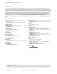
RESET
Monitoring Circuit
M1
n.c.
M2
EZ-LIGHT Logic
C B A 0V
3 1 5 8 6 4 2 7
8-Pin M12 Female Cordset
EZ-LIGHT Logic
C B A 0V
3 1 5 8 6 4 2 7
8-Pin M12 Female Cordset
M1
M2
Machine
Control
ES-FA-11AA
A1
A2
S33
S34
14
24
32
13
23
31
S11
S21
S22
S12
+24V dc
(optional)
+24V dc 0V dc
K1 K2
E-Stop #1 Status
E-Stop #n Status
Figure 1. Illuminated models - example hookup
NOTE: Refer to the ES-FA-11AA E-Stop Safety Module datasheet (p/n 60606) for complete safety
module installation information.
SSA-EB Series Lighted Emergency Stop Push Buttons
4 www.bannerengineering.com - Tel: +1-763-544-3164 P/N 162754 Rev. D