
Datasheet


8-Pin Threaded M12/Euro-Style Cordsets―Double Ended
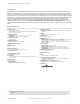
Model (8-pin/8-pin )
4
Length Style Dimensions Pinout
DEE2R-81D 0.31 m (1 ft)
Female Straight/
Male Straight
40 Typ.
ø 14.5
M12 x 1
44 Typ.
ø 14.5
M12 x 1
Female
5
4
3
2
8
1
7
6
Male
5
6
7
1
8
2
3
4
DEE2R-83D 0.91 m (3 ft)
DEE2R-88D 2.44 m (8 ft)
DEE2R-815D 4.57 m (15 ft)
DEE2R-825D 7.62 m (25 ft)
DEE2R-850D 15.2 m (50 ft)
DEE2R-875D 22.9 m (75 ft)
DEE2R-8100D 30.5 m (100 ft)
1 = White
2 = Brown
3 = Green
4 = Yellow
5 = Gray
6 = Pink
7 = Blue
8 = Red
See Banner Engineering catalog or www.bannerengineering.com for additional models and complete information.
Series Hookup Cordset Solution
This interconnection solution allows for quick hookup of a series of string emergency stop buttons. For the models listed
below, Branch #1 and Branch #2 are 300 mm (12 in) in length and the length of the trunk is listed below.
WARNING: Intentional Defeat
The CSS Series Hookup Cordsets must be installed so that they cannot be easily defeated.
Ensure that mounting and routing of the cordsets that are connected to the Trunk, Branch #1, Branch
#2, and the E-Stop QD connector does not allow access to the QD connectors or allow improper
connection bypassing the function of the Emergency Stop.
RESET
Monitoring Circuit
M1
n.c.
M2
M1
M2
Machine
Control
ES-FA-11AA
A1
A2
S33
S34
14
24
32
13
23
31
S11
S21
6 = CH1a (Pink)
5 = CH2b (Gray)
4 = CH2a (Yel)
8 = CH1b (Red)
1 = NO AUX (Wht)
2 = +24V dc (Brn)
3 = STOP Signal (Grn)
7 = 0V dc (Blu)
S22
S12
+24V dc 0V dc
K1 K2
+24V dc
(optional)
4
Standard cordsets are yellow PVC with black overmold. For black PVC and overmold, add suffix "B" to model number (example, DEE2R-81DB)
SSA-EB Series Lighted Emergency Stop Push Buttons
8 www.bannerengineering.com - Tel: +1-763-544-3164 P/N 162754 Rev. D