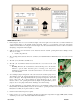
Electric Mini-Boiler TM Installation & Operating Instructions Model EMB-W-9 9 kW 2 GPM minimum flow Application - Low temperature, low pressure, radiant underfloor heating systems. includes a factory installed WarmFlo® aquastat. This model Comment - If this application is for traditional hydronics heating requiring temperatures greater than 14Ø and capacities larger than shown above, contact factory for other Electro-Boiler product series.
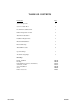
TABLE OF CONTENTS Description Page System Components 1 System or Water Flow 1 Room Thermostat Placement 1 Built in Temperature Control 2 Water Flow Calculation 2 Installation Requirements 2 Mechanical Installation 3 Electrical Hookup 4 Water Fill Procedure 6 Operational Tips 7 Troubleshooting Helps 8 Drawings: Piping, install kit Hook-up Internal Wiring (reference information) Schematic, one line Sensor Installation Zones Boiler Accessories 10/22/2008 BX304 BH304 BS304 BS309 BD705
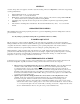
GENERAL As stated, this product series applies to underfloor hydronics heating. The basic components for an electric energy heating system typically includes: 1. 2. 3. 4. 5. Electric Mini-Boiler itself – covered by this manual Thermostat control – covered by this manual Plumbing kit or piping material at the boiler itself - Can be ordered as a kit, reference catalog number EMB-PK. These items are shown on plumbing installation drawing BX304.
TEMPERATURE CONTROL The hi-limits within this unit are for safety purposes only. The system installation must have a proper responding slab sensing thermostat to properly turn the boiler on and off. If the water flow is greater than the minimum GPM specified, this boiler should not reach hi-limit and the hydronics loop should continue to flow in the normal heating pattern until the operating slab stat is satisfied.
CAUTION Hazards or unsafe practices could result in property damage, product damage, severe personal injury and/or death. 3. Remember, safety is the installer’s responsibility and the installer must know this product well enough to instruct the end user on its safe use. Safety is a matter of common sense - - a matter of thinking before acting. Professional installers have training and experienced practices for handling electrical, sheet metal, and material handling processes. Use them.
Boiler/Plumbing Kit Placement – This model series is wall hung and the vessel must be vertical. The plumbing kit items are located adjacent to the boiler housing itself as shown on drawing BX304. For future servicing, the unit itself must be installed a minimum of 18” above the floor. The elements are screwed in from the bottom. Allow adequate space for cover removal and maintenance. Expansion Tank - As a closed loop hydronic heating system, a minimal expansion tank is required.
WARNING USE ONLY COPPER WIRE FOR CONNECTION TO THE CIRCUIT BREAKER TERMINALS AND INSIDE THIS PRODUCT’S CABINET. WARNING TO AVOID THE RISK OF ELECTRIC SHOCK OR DEATH, WIRING TO THE UNIT MUST BE PROPERLY GROUNDED. FAILURE TO PROPERLY GROUND THE UNIT CAN RESULT IN A HAZARD LEADING TO PERSONAL INJURY OR DEATH. 3. Circulating Pump – the two screw terminals (orange wires) represent a switch closure (see drawing – 10-amp maximum) to operate the circulating pump motor.
2. Impurities within a closed loop hydronics boiler are considerably less damaging than the typical domestic water heater. In a closed loop electric boiler, the water impurities “boil out” and the system essentially reverts to pure water. As a closed system, this “pure water” becomes the operating mode. In the case of domestic water tank, there is always new water entering with new impurities. 3.
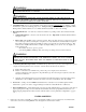
Figure 1 OPERATIONAL TIPS 1. Indicator lights – there is a set of four indicator lights on the lower right corner of the front cover with an identical set of four indicator lights on the internal circuit board itself. Figure 1 is a reproduction of the front decal giving definition and information for using these indicator lights. Note the statement that there must be a call for heat before attempting to interpret the indicator lights. 2.
WARMFLO AQUASTAT OPERATION Sensor cable installation – see previous paragraph, Mechanical. Determine from floor tubing supplier design outline the desired floor temperature. Typically this relates to floor covering and tube placement design. Set the aquastat set point for desired warm water outlet. The temperature set point is selected by a small screwdriver switch on the control board.
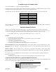
MINI-BOILER HOOKUP (EMB-W-9) NOTES: 1. THIS UNIT HAS A FACTORY-INSTALLED BLUE JUMPER THAT BYPASSES THE LMC MODE. WHEN LMC OPTION IS USED, REMOVE JUMPER BEFORE INSTALLING. FUSE SHOWN 2A WITH MAX. COVER REMOVED NO LIGHTS 3. J4 OPERATE MUST ON-BOARD INTERNAL WIRING 2. SHOWN 4. ANY HAVE LED 2-WIRE ONLY ON THERMOSTAT EXTERNAL LED PLUGGED TO CALL IN FOR OR HEAT. JUMPERED FOR OPERATE.
MINI-BOILER HOOKUP (EMB-W-9) MULTI-ZONE, ANY NUMBER OR SIZE. ELECTRO-STAT ELECTRO-STAT (ES-24-BR) (ES-24-BR) ZONE 1 ZONE 2 4-WIRE 4-WIRE THERMOSTAT THERMOSTAT C GREEN CABLE GREEN CABLE W R C W R SLAB SENSOR SLAB SENSOR #5616 TRANSFORMER C FUSE SHOWN COVER NO 2A WITH MAX. 24V REMOVED INTERNAL 120V POWER FROM PUMP CB R WIRING SHOWN TYPICAL ZONE W 4/A2 M YEL 2/T1 RED NO COM T1 W3 T2 T11 ARL NO 205 N1 TB3 CURRENT RATING.
ELECTRO-BOILER SENSOR INSTALLATION Once the pipe well has been installed. Liberally apply the supplied heat compound around the tip of the Warmflo sensor. Then gently insert sensor into pipe well. Note: Using the tip of your finger, or another non-piercing object will aid in the insertion of the rubber grommet. Once the grommet has been inserted into the well gently press the sensor until it reaches the bottom of the pipe well. Installation complete.
WARMFLO BOILER ZONE VALVE HOOKUP ELECTRO-STAT ZONE ELECTRO-STAT 1 ZONE SLAB STAT SLAB ELECTRO-STAT 2 ZONE STAT SLAB 4-WIRE 4-WIRE 4-WIRE THERMOSTAT THERMOSTAT THERMOSTAT CABLE CABLE STAT CABLE R C W GREEN W GREEN GREEN C 3 R SLAB SENSOR SLAB C W R SENSOR SLAB TO TRANSFORMER ADDITIONAL SLAB R 120V SENSOR TYPICAL 24V W C C YEL YEL M - 2-WIRE - ISOLATED - EXAMPLE: V8043F STAT END STATS (ZONES) ZONE VALVE SWITCH YEL W HONEYWELL YEL C SERIES OR Y
WARMFLO BOILER ZONE VALVE HOOKUP ZONE SLAB 1 ZONE STAT EI P/N #7101 2 ZONE SLAB EI P/N #7101 EI P/N #7101 2-WIRE 2-WIRE 2-WIRE THERMOSTAT THERMOSTAT THERMOSTAT CABLE CABLE CABLE R R IN-SLAB IN-SLAB IN-SLAB SENSOR SENSOR SENSOR W/ 10 FT. W/ 10 FT. W/ 10 FT.
BOILER ACCESSORIES ZONE CONTROLLER This will simplify your wiring and make zoning applications much easier. In addition, enhanced communicating features have the ability to stage the electric boiler based upon the connected zone capacity.
TWO SUPPLY WATER TEMPERATURE REQUIREMENT • Handled as the priority zone on multi-zone (EB-ZEA-1) or two pump (EB-Z2P) controllers • Priority switch on, zone 1 active - TS boiler automatically changes to 150° (or selection 176°) supply water setting • • All other zones are held off With zone 1 satisfied or 60-minute timeout, the boiler automatically returns to the preset temperature and reacts to the other zones Low Temp High Temp Radiant, slab Radiant, staple up Radiant, slab Baseboard Radiant, s
Electro Industries, Inc. Limited Product Warranty Effective October 1, 2007 Electro Industries, Inc. warrants to the original owner, at the original installation site, for a period of two (2) years from date of installation, that the product and product parts manufactured by Electro Industries are free from manufacturing defects in materials and workmanship, when used under normal conditions and when such product has not been modified or changed in any manner after leaving the plant of Electro Industries.
THESE WARRANTIES DO NOT COVER: 1. Costs for labor for removal and reinstallation of an alleged defective product or product parts, transportation to Electro Industries, and any other materials necessary to perform the exchange, except as stated in this warranty. Replacement material will be invoiced to the distributor in the usual manner and will be subject to adjustment upon verification of defect. 2.