
EB-NB Installation Manual

12/28/2018 8 BI804
Additional Safety Control Options
Remote or boiler room stop switch – a field provided stop switch with a normally closed contact can be
easily wired into TB1-1 and 2. Simply remove the factory provided black/yellow jumper between 1 and 2
and connect the normally closed stop switch. If it is a push/pull (internal to stop switch), the alarm
monitor LED will identify this function.
Additional external low water cutoff – this can also be looped into the TB1-1 and 2 mentioned above.
If the external LWCO has a manual reset function, it will need to be reset at that component.
Alarm monitor “EM stop” is the monitor for opening TB1-1 and 2.
External water flow switch – this closed to flow contact can also be added to the TB1-1 and 2 black/yel
jumper loop. Its function will keep all power contactor coils de-energized whenever 1 and 2 are open
(also sets alarm 4).
Another suggestion for hot boiler and continuous pump, use the water flow switch as a contact for
opening the R and W system on switch (see Electrical Installation – Preparation section, bottom
paragraph).
Multiple Boilers, Same System
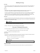
Piping/pumps – boilers are plumbed in parallel, each flowing equally into a header or primary loop.
Steps need to be taken to make sure there is an evenly divided flow into the header, related to the number
of boilers in parallel. Depending upon pump sizing, the primary loop pumping system could be equal size
pumps at each boiler supply pipe. See page 1 chart for required flow through each vessel.
Boiler identification – each boiler is the same model and the standard equipped unit. Water flow design
and operation will be considerably easier if each boiler is the same kW size and in fact the exact same
model number, see page 1 chart.
System or boiler room temperature control – each boiler has its own safety LWCO, HL1, and HL2
temperature limits. The system temperature controller must be external and have a 0-10VDC analog
output or a building energy management system. The temperature sensing for this central temperature
controller would be in the header pipe away from any individual boiler. The output of this system
temperature controller (0-10VDC) is connected to (in parallel to each boiler) the control board.
NOTE: If this is a multiple boiler configuration of two, and both are Electro Industries’ Industrial
Boilers, each boiler has a built-in LEAD/LAG control. This allows the two boilers to spread the system
demands (system cycles) evenly between the two boilers. This does require special system setup. If
application is greater than two boilers, a field provided controller must be added.
Dual Boilers/Dual System
Plumbing/valving – suggestion is represented on drawing BX803.
Utility load control – when a utility receiver is connected to the system as shown on BH801, the electric stages
are terminated and a switch closure is made on “SB OUT” connection. This can be connected directly to the
fossil fuel boiler R and W terminal. In this case the R and W at the Industrial Boiler module controls “SB OUT”
connection. The fossil fuel boiler should not have R and W jumpered or go to a room type thermostat.