
EB-NB Installation Manual

12/28/2018 4 BI804
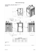
Piping Connections
The pipe extensions outside of the boiler cabinet are permanently welded to the vessel. Caution must be
used to make sure field piping is properly threaded so damage does not result requiring field repair or a
replacement (not under warranty) vessel.
New Installation
Piping connections and valves must comply with state and/or local codes, in addition to compliance with
ANSI piping requirements.
Retrofit or Dual Systems
Make sure there is adequate valving between the two boilers for proper individual operation or proper
backup boiler room operation plan. Drawing BX803 represents the minimum valving suggestion by the
factory.
The control design includes provisions for utility load control, also see pages 8 and 9.
Safety Pressure Relief Valve
As factory installed, there must be a 1” pipe between vessel and pressure relief valve. The provided relief
valve must be mounted with the relief lever up. Field add necessary drain pipe extension to a proper drain
location within the boiler room. 30 psi relief valve included with standard models. Special order 125 psi
models include 125 psi relief valve.
Vessel Drain Port/Inspection Opening
The left side bottom 1” pipe is provided for maintenance or vessel servicing drain, provide necessary
extension/access.
A 3” inspection opening is provided on the lower left side of the boiler.
Purge Eliminator/Air Vent/Expansion Tank, Etc.
All standard, best practices, hydronic components must be field provided and installed external to this
unit. This unit has an internal safety low water cutout and the necessary temperature safety cutout and
operating controls, see operating section. However, this unit does not have an interlock flow switch or
boiler room emergency stop switch. See Electrical Installation for terminal block connection provisions.
Expansion tank must be sized for the maximum Btu/h capacity.
This unit includes a small ½” integrated air vent used to assist in venting potential trapped air at the top of
the boiler vessel. It is not intended to be used as a system air vent.
Direction of Flow
The left side inlet is the return water and the top outlet is the supply.
System Flush/Boil-Out
Prior to final system fill and start-up, the entire system (including the boiler) must be thoroughly
flushed. Performing a pre-flush and chemical system flush significantly reduces the chances of any debris
or impurities causing premature failure to the boiler and its associated system components.
It is recommended to first flush the system with clean water to remove any major debris in the system.
Care should be taken to isolate the circulating pumps to avoid contaminating the pumps during this
process. Then proceed with a chemical flush to remove the remaining fine particles in the system. It is
recommended that a commercially available boil-out compound be used in this procedure. Follow the
manufacturer’s instructions for specifics regarding the boil-out procedure.