
EB-NB Installation Manual

12/28/2018 6 BI804
Electrical Installation – Preparation
Typical external requirements – depending upon the electrical utility servicing the site, this model
typically is added to the general service as a 3 Ø “Y” source.
If the service is delta (unbonded neutral) with dedicated utility transformer, verify ground fault, a
ground fault monitor may be required to maintain warranty.
See nameplate and/or Specification page for 3-phase operating voltage rating and kW rating to
determine service entrance size.
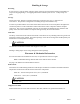
Service feed – depending upon model, but generally this unit is fed by two service entrance 3-phase
feeds. These are not parallel feeds, the internal distribution blocks are independent loads having a fixed
number of electric element stages apply to each feed.
See page 1 for service feed sizing and distribution.
External or service wire size – the internal service feed distribution blocks are rated for copper or
aluminum wire. It is the installer’s responsibility to have proper electrical connection at this main unit’s
distribution block to prevent any overheat within the main unit cabinet.
Wire insulation rating within the main unit cabinet must be 75° C or greater.
Wire size, protection, routing, temperature rating, etc. is the responsibility of the installing
contractor, local and national codes. See nameplate and/or page 1 Specification for voltage and
main unit kW rating.
Safety grounding – a single point grounding electrode system must be established for the facility. Both
the transformer cabinet and the general service transformer grounding conductor with the main building
service entrance grounding lug must be all bonded to the same facility grounding electrode system.
The main unit ground lug, next to the service feed distribution block must be connected to the
facility grounding electrode system, per NEC or CEC codes. The conductor size from these main
unit internal ground lugs depends upon the service feed size and must be per NEC or CEC code.
System setup – this is further defined in its own section, but there are many setup possibilities relating to
various applications, control options, and troubleshooting. These factory defaults are set up from the
factory, so system setup is not necessarily required but may be necessary if the “out of the box” settings
from the boiler do not meet the application.
Set Point (outdoor sensor not connected)
Base temp, high mass – 90° F (32° C)
Base temp, low mass – 120° F (49° C)
Maximum stages, coordinates with the number of stages for the shipped model number
External R-W device – a contact closure is required between R and W for heat active operation. Do not
simply jumper R to W or use for the load control relay. Utility load control is provided at the left blue
jumper TB. In the case of hot boiler this is probably the system on external pump switch. As a
minimum, suggest a flow switch contact proofing the continuous pump. Product liability and warranty is
exempt if R to W has a jumper wire and pumps fail causing no flow.