
EB-NB Installation Manual

12/28/2018 7 BI804
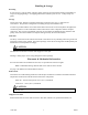
Electric Installation – Power Feed
Using the information from the previous section, it is the installer’s responsibility for proper 3-phase
power feed and safety grounding per NEC and CEC electric codes.
See page 1 for distribution between the two feeder terminal blocks. Feed #1 always has 8 or less
stages.
Prepare service conductor cables and torque as required within the terminal block as required for
the installer selected cable type and size.
Some local codes and CEC electric code require single disconnect and single feed. If this is the case,
installer must provide disconnect with multiple feeds per drawing BH802.
Electrical Installation – Control Box
120, single phase, 15A general service or main building service panel source – provide and route to
the upper left corner CB and neutral block.
Note: A green wire ground from this general service panel is not required or suggested because the ground
lug within the control box is connected to the main safety ground in the main unit. Based upon page 6
grounding details, the main unit ground lug is bonded to the building grounding electrode system.
Remote operating thermostat or operating device – there must be a closed contact between R and W to
initially active the electric elements and the pump relay on the board. This also activates the Sequencer
for the staging contactor.
If operating as a hot boiler with continuous pump, typically a system on/off switch controls the R
and W. Provisions need to be made to make sure it is continuous pump, suggest with this
arrangement a flow switch is connected in this R and W contact loop.
Main circulating pump – determine whether pump is continuous on or is operated by the R to W input
signal, use the pump relay (the larger cube relay) on the board. When using the top two terminals this has
a 25-amp, 120V or 240V, rating. Route and clearance protect these line voltage wires in and out of the
control box as required by NEC/CEC code. This contact can be used to drive an external contactor for 3-
phase or higher voltage pumps.
Utility load control – if this is a required part of this installation, remove the left blue and route two
wires to the utility load receiver.
Outdoor sensor (OT) – this product is factory shipped with a 25’ (7.6 meter) cable and OT sensor. It has
three tabs on the board, bottom left. From the factory, this sensor is shipped loose. If the outdoor sensor is
required for the application, simply connect the sensor to the board (power cycle required).
Note wire colors and labeling, sensor cable can be disconnected for installation. Do not route OT sensor
cable along line voltage Romex or line voltage wiring. Crossing is okay, but when there is a somewhat
parallel route the sensor tip must be installed up, cable end must remain dry. Install at any shaded sun
outside temperature location.
Fault detector – if 3-phase Delta service, a ground fault monitor may be required.