
Product Manual


05/19/2016 7 BI514
MECHANICAL INSTALLATION – UNDER-FLOOR RADIATION
CAUTION
Electro Industries Inc. requires the use of dielectric isolation between the boiler vessel supply
and return piping when the boiler is plumbed using copper or any other dissimilar metal.
Damage to the vessel caused by galvanic corrosion voids Electro Industries’ warranty.
Reference drawing BX501
1. With the typical radiant floor system, a dual heat backup boiler is uncommon. If a backup boiler is
required, please reference “Mechanical Installation – Dual Heat” section.
2. Unpack the Electro-Boiler, the safety relief and pipe fittings are packed within a small carton. The
safety relief is plumbed to the ¾” pipe as shown on BX501 (or may be part of other components
shown on BX502, page 2).
3. The Electro-Boiler must be positioned with the vessel vertical. The water IN/OUT ports must be at
the top. The unit will not function properly with the vessel in a horizontal position.
NOTE: Mount at least 20 inches above the floor to allow element removal and service at the
bottom.
4. The plumbing components and plumbing layout shown on drawing BX502 have been very carefully
chosen and should be plumbed as shown. When following this diagram, the water fill procedure
becomes very simple and almost guarantees the removal of all air or prevents air locking problems.
Experienced hydronic heating installers may be able to eliminate some components but the inclusion
of these components guarantees installation and initial operating success.
5. The vessel is factory constructed with a “air trap” chamber at the top of the vessel, connected to the
¾” pipe and arrangement shown on BX502, page 2.
6. The key mechanical components required include:
Expansion Tank – as a closed loop hydronic heating system, a minimal expansion tank is
required. This can be an air diaphragm tank as provided in the plumbing kit or a basic
“empty” tank where air is compressed at the tank top.
Inlet Temperature Gauge – recommended to observe the operation of the system.
Air Vent – install with the pressure relief valve as shown on drawing BX502, page 2 or part
of the air eliminator shown on BX502, page 3.
Inline Air separator – this can be installed ahead of the pump with the expansion tank
moved to this point. However, the vessel designed air trap and the piping arrangement
leading to the air bleeder shown on BX502 page 2 works very well.
Pressure Safety Valve – this is required and is furnished as a loose component with the
boiler unit itself. Failure to install the provided, 30 PSI, pressure relief valve as shown void
warranty and the CSA product listing. During purging there is a requirement to bleed out the
initial air within this ¾” pipe leg by manually holding open the relief valve. Add the
necessary pipe extension to the relief valve to prevent water damage on this unit or
surrounding area.
Gate Valve/Drain Valve – these are for servicing and easy fill purposes.
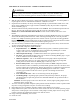
Circulating Pump – depending upon system lift and system loop resistance, the proper
circulating pump is required to guarantee the minimum GPM flow as specified in Table I –
Electro Boiler.
Comment: Circulator pump can be in the outlet or inlet. Newer, higher quality pumps seem to
work better in the “supply” line.
7. To ensure safe boiler operation adequate system pressure must be maintained. Some expansion tanks
may have an integral regulator and “port” for water source hookup.
8. Depending upon water conditions, determine whether water additives are necessary.
9. Purge and fill water system. Do not allow the electric element to come on until the system is purged
and you have verified proper water circulation. If the pump is needed, jumper the two orange wires
in order to operate the pump directly from its own 120 volt source.
10. Purge each loop individually, one at a time.
11. Check for leaks.