ELECTRO-BOILER TS Series INSTALLATION & OPERATING INSTRUCTIONS Model APPLICATION: EB-(S or WX)-13 EB-(S or WX)-18 EB-(S or WX)-23 EB-(S or WX)-27 This Electro-Boiler is factory equipped with WarmFlo smart controller. WarmFlo automatically regulates outlet water temperature based on a desired output temperature set point. Primary application is any hydronic water heating system where reduced flow or radiation can cause overheat conditions (example, zones).
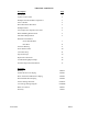
TABLE OF CONTENTS Description Page Introduction 1 System or Water Flow 2 Multiple Zones & Radiant Temperatures 2 Zone Controller 2 Room Thermostat Placement 3 Multiple Boilers 4 Two-Temperature Operation or Feature 5 Boiler/Plumbing Kit Placement 5 Installation Requirements 5 Mechanical Installation Under-Floor Radiant 7 Dual Heat 8 Electrical Hookup 9 Water Fill Procedure 10 Controller Setup 11 Operational Tips 13 Replacement Parts List 15 Troubleshooting/Repair Helps 16
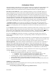
INTRODUCTION With this WarmFlo configuration, the electric heating elements are automatically staged/modulated and controlled to establish a fixed outlet water temperature. This outlet temperature is sensed by the WarmFlo controller and is controlled to achieve and maintain the boiler’s set point temperature. First-time or non-routine user – before attempting installation or setup of a WarmFlo product, we suggest studying the last section of this manual, Operation Information and Technology Definitions.
SYSTEM OR WATER FLOW In order to prevent hi-limiting and assure full 20+ years parts life, the piping system/basic plumbing/circulator pump must be arranged to provide flow greater than minimum GPM shown in Table 1. If zoned system, this applies when the smallest zone is operating. NOTE: Since this is an automatic temperature sensing system, both sensors and the complete control wiring are required before using or turning on this Electro-Boiler.
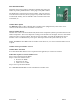
2. Prevents over control or false staging up and down when the temperature sensors are attempting to regulate – since Electro Industries’ zone controllers also have staging “smarts”, the addition of the zone controller will provide smoother boiler temperature control. The zone board has a dial switch for each zone and the installer selects one of four zone capacity sizes.
MULTIPLE BOILERS This boiler series now includes a method for automatically staging any number of parallel-plumbed boilers. Order plug-in relay EB-C-STG5. The thermostat is connected only to the first boiler, when all stages are on for more than 5 minutes, this new plug-in relay module turns on the next boiler (R and W), and a second EB-C-STG5 could be used to turn on the third, etc. Outdoor Reset Option The EB-WX-** boiler comes equipped with an outdoor sensor (shipped loose).
TWO-TEMPERATURE OPERATION OR FEATURE When using Electro’s zone controller in priority mode, the boiler system can automatically raise the outlet temperature with zone 1 calling. This is setup for default of 150° or pulling a jumper peg the high temperature value is 176°. See appropriate zone controller installation manual for details. BOILER/PLUMBING KIT PLACEMENT This model series is wall hung and the vessel must be vertical, drawing BX501.
phone assistance) relating to the gas/oil furnace are provided as comments of assistance and “helps” only. CAUTION Hazards or unsafe practices could result in property damage, product damage, severe personal injury and/or death. 3. Remember, safety is the installer’s responsibility and the installer must know this product well enough to instruct the end user on its safe use. Safety is a matter of common sense - - a matter of thinking before acting.
MECHANICAL INSTALLATION – UNDER-FLOOR RADIATION CAUTION Electro Industries Inc. requires the use of dielectric isolation between the boiler vessel supply and return piping when the boiler is plumbed using copper or any other dissimilar metal. Damage to the vessel caused by galvanic corrosion voids Electro Industries’ warranty. Reference drawing BX501 1. With the typical radiant floor system, a dual heat backup boiler is uncommon.
MECHANICAL INSTALLATION – DUAL HEAT CAUTION Electro Industries Inc. requires the use of dielectric isolation between the boiler vessel supply and return piping when the boiler is plumbed using copper or any other dissimilar metal. Damage to the vessel caused by galvanic corrosion voids Electro Industries’ warranty. Reference drawing BX504 1. Unpack the Electro-Boiler. The safety relief and pipe fittings are packed within a small carton. 2.
ELECTRICAL HOOKUP Reference drawing BH512 1. 240 Volt Heating Power – route and install the proper current carrying conductors from service panel fuse or circuit breaker. See Table 1 – Electro-Boiler and/or product nameplate for ratings. These models contain built-in circuit breakers and meet the requirement for local disconnect for appliances greater than 10 kW. Connection is at the circuit breaker terminals.
7. Zone Valves or Zone Pumps – see Zone Controller section for options. WARNING THE END SWITCHES FROM THE ZONE VALVES MUST BE AN ISOLATED CONTACT WITH NO VOLTAGE PRESENT ON THESE WIRES OR SCREW TERMINALS. THIS IS VERY IMPORTANT TO MAKE SURE THERE ISN’T ANY INTERFERENCE OR FEEDBACK BETWEEN THE TRANSFORMER OPERATING THE ZONE VALVE SYSTEM AND THE TRANSFORMER WITHIN THIS ELECTRO-BOILER PRODUCT. ONCE THIS HAS BEEN DETERMINED, ALL END SWITCHES ARE SIMPLY PARALLELED WITH THE TWO WIRES GOING TO “R” AND “W”. 8.
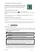
12. Optional – energize circulating pump during this fill operation. The water pressure from the household system and as plumbed should typically flow through the circulating pump without the pump running. COMMENT: Purge one loop at a time. CONTROLLER SETUP Red dial switch, front panel: Non outdoor reset –simply set the “knob” to the desired outlet temperature shown here and on the front panel decal.
Staging/Modulating Jumper The control board on the TS Standard Series boiler is a universal controller with the capability of interfacing with many different models of TS Electro Boilers. The correct setting of this jumper is determined on the model of boiler you are working with. If you’re working with an EB-WX-**, this must be set to “MODULATE”. If you’re working with an EB-S-**, this must be set to “STAGING”.
OPERATIONAL TIPS Energy Selector Switch If this system does not have a standby operating (gas or oil) boiler, this switch must always be in the “normal” position. To activate standby boiler, simply position front panel switch to “standby”. Monitor Lights, Front Panel 190°F AUTO RESET LIMIT, red – this will only illuminate when the vessel hi-limit opens due to excessive high water temperature. This hi-limit is self-resetting. BOILER POWER, green – basically this is illuminated at all times.
Manual Reset, Hi-Limit At the top of the vessel there will be either two or three surface mount hi-limits preset at 205° F. There is no light indicator associated with these safety hi-limits. Also these 205° F safety limits break the L2 current carrying 240-volt wire going to the elements. Reset involves locating a small shiny lever or metal tab protruding on the side of the black safety limit base. This small tab is pressed inward approximately 1/8” to “snap in” the contacts.
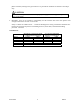
Replacement Parts WFSB WFS25F EB5623 UFUSE0442 4038KIT 5127 5535 5537 5453 5456A 5652 5650 EB5520 5541 05/19/2016 Water sensor, 3 ft. Outdoor sensor (OT) Controller, temperature sensing 5-amp, fast blow mini-automotive fuse Triac switch module Heating relay Safety hi-limit, manual, 205° First hi-limit, auto-reset, 180° Relief valve, 30 PSIG Gauge press/temperature 60A SQ D circuit breaker 30A SQ D circuit breaker Electric element, 240, 4.
TROUBLESHOOTING/REPAIR HELPS 1. This WarmFlo controller contains several interference suppression components, but as an electronic logic product, unpredictable and unusual transients or interference may sometimes cause strange results. If the WarmFlo controller is “acting strange”, one immediate step would be power down reset. Simply turn off boiler power or breaker number 1, when the green LED goes out, count to 1Ø, and re-energize power supply. 2.
OPERATIONAL INFORMATION In order for the installer to completely understand the WF II functions and operational sequence it is recommended to thoroughly read and understand the information below. This knowledge can help in determining settings that can be set according to the end customer’s needs.
ELECTRO-BOILER DUAL HEAT PIPING DIAGRAM TO SYSTEM FROM SYSTEM SAFETY INLET VALVE #5453 GATE 1 VALVE DRAIN VALVE (THREADED INTO TEE) IN OUT WATER SUPPLY VALVE AUTO FILL VALVE EXPANSION (REGULATOR) TANK WATER SUPPLY CONNECTION OUT IN ELECTROBOILER NOTES: 1. LOOSE PARTS SHIPPED WITH BASIC BOILER MODEL. 2. IF WOOD BOILER, REVERSE ORDER (ELECTRIC FEEDS WOOD). OIL/GAS BOILER (WITH PUMP) 2 3. MINIMUM 20" SPACING BETWEEN FLOOR AND BOTTOM OF BOILER. DRAIN 3 ELECTRO INDUSTRIES, INC.
BOILER ACCESSORIES ZONE CONTROLLER This will simplify your wiring and make zoning applications much easier. In addition, enhanced communicating features have the ability to stage the electric boiler based upon the connected zone capacity.
TWO SUPPLY WATER TEMPERATURE REQUIREMENT • Handled as the priority zone on multi-zone (EB-ZEA-1) or two pump (EB-Z2P) controllers • Priority switch on, zone 1 active - TS boiler automatically changes to 150° (or selection 176°) supply water setting • • All other zones are held off With zone 1 satisfied or 60-minute timeout, the boiler automatically returns to the preset temperature and reacts to the other zones Low Temp High Temp Radiant, slab Radiant, staple up Radiant, slab Baseboard Radiant,
Electro Industries, Inc. Residential Limited Product Warranty Effective November 1, 2009 Electro Industries, Inc. warrants to the original owner, at the original installation site, for a period of two (2) years from date of original purchase, that the product and product parts manufactured by Electro Industries, Inc.
CONDITIONS AND LIMITATIONS: 1. This warranty is limited to residential, single family dwelling installations only. Any commercial or multi-unit dwelling installations fall under the Electro Industries Commercial Limited Product Warranty. 2. Electro Industries, Inc. shall not be liable for performance related issues resulting from improper installation, improper sizing, improper duct or distribution system, or any other installation deficiencies. 3.