
Product Manual

05/19/2016 1 BI514
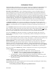
INTRODUCTION
With this WarmFlo configuration, the electric heating elements are automatically staged/modulated and
controlled to establish a fixed outlet water temperature. This outlet temperature is sensed by the
WarmFlo controller and is controlled to achieve and maintain the boiler’s set point temperature.
First-time or non-routine user – before attempting installation or setup of a WarmFlo product, we
suggest studying the last section of this manual, Operation Information and Technology Definitions.
Even though this WarmFlo configured unit adjusts outlet temperature independent of water flow and
prevents high limiting even with marginal water flow, it is still very important that the hydronic system be
correctly designed for the building, the total heat loss requirement, and proper hydronics design and
installation practices. This boiler is the energy source for the water flow and radiation system. If the
water flow and radiation systems are not adequate for the Btu/h heat loss of the building, installing the
Electro-Boiler with WarmFlo will not necessarily supply the comfort and heating for the building.
“Cold boiler” notation – do not, under any circumstances, simply jumper R and W and allow the
temperature sensing controller to operate this Electro-Boiler as a “hot boiler”. Unless there is at least 2
GPM flow, the staging delays will cause temperature overshoot and could open up the manual reset
limits.
In most dual heat installations this Electro-Boiler is plumbed in parallel with an existing oil, gas, or wood
boiler. The Electro-Boiler is generally at the gas/oil outlet; but for wood, the Electro-Boiler must be on
the inlet sides. The standby boiler cannot be operated as “hot boiler”. This will defeat the Electro-Boiler.
Rewire as required, standby boiler is turned on from the brown wires (included in this boiler).
In the case of existing fossil fuel boiler conversions, it is assumed the expansion tank, valving, air
bleeder, and circulation pump are in place, in good operating condition, and adequate for the overall
system design.
In the case of new installation (floor radiant or baseboard), use standard hydronics water heating practices
for the necessary expansion tank, air bleeder, valving, water pump, etc., sized for the total capacity of the
system. The Electro-Boiler is turned on with an “R and W” closure from the system wiring.
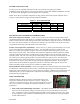
208 Volt application – the elements within the standard product are rated a 240 volts. If operating at
208, there will be approximately 25% reduced capacity. The internal transformer may or may not
adequately operate the control system from a 208 source. Voltage measurements between “R” and “C”
must be 22VAC or greater when the system is in the complete operational mode. True 3-phase, 208-volt,
models are available in the WarmFlo series, models EB-WX-13-2 and EB-WX-27-2, contact factory.
In the case of under floor radiant heating, the basic components for the electric energy, heating system
typically includes:
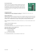
1. Electric boiler itself, drawing BX501 – covered by this manual.
2. Plumbing kit or piping material at the boiler itself – can be ordered as a kit.
EB-BK-TS – shown on plumbing installation drawing BX502, pages 1 and 2.
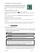
EB-PK-TS – shown on plumbing installation drawing BX502, page 3.
3. Circulating pump – typically sized for head pressure and system flow requirement, typical
catalog number EB-P2. Large pump maybe required for 23 or 27 kW.
4. The under floor circulating tubes and manifolds – provided and manufactured by others, not
covered in this manual.
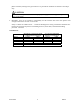
APPROVED TUBING/PIPING
When plumbing this boiler and its peripheral parts to the loop system, all plumbing parts and/or tubing
must be sealed to prevent entrance of oxygen.
Use only tubing or polyethylene tubing with oxygen Diffusion Barrier.