
Operating instructions

04/03/2009 17 EI204
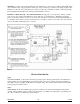
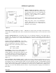
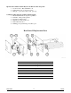
Reduced HeatChoice output – (figure 14) the white/
blue jumper wire located on the upper right hand side
of the control board (W1, W2) is designed to drop half
of the HeatChoice heating elements when opened.
When the jumper is opened stages 2, 4, and 5 are
dropped, when applicable.
Application: This option can be useful for
multiple zones, load shed, outdoor thermostat,
or any other external contact closure when
needed to cut the output in half.
Option: Purchase EB-5415A (hookup drawing
EH020) for multiple zone applications, call factory for details.
Total electric – in this case there probably is no utility load control receiver, simply keep the two blue wires
shorted with wire nut and the furnace burner is probably disabled. Remove the SOT jumper located on upper
right hand side of the HeatChoice control board. By removing the SOT jumper, this will prevent the control
board from timing out during a heat call and attempting to turn on the standby heat source. The furnace is only
used as a blower source. The 240 element power must come from the appropriate size CB breakers within the
general service panel.
Time-of-Use or Time-of-Day – installation is basically the same as the previous dual heat/load management
concept, except the 240 power source probably comes from CB’s within the single general service panel. The
control for the blue wires can be an internal contact within the TOU meter or a user provided time clock with its
time function coincident with the TOU on/off-peak time.
Note 1: When using an external time clock make sure the blue wires go to an isolated contact and make
sure the time clock is not inadvertently providing line voltage to one of the blue wires. Line voltage
will result in instant circuit board failure.
Note 2: Some TOU or limited off-peak internal control contacts (Xcel, Wisconsin) have N.O. = off-
peak logic. In this case connect to terminals X1 and R on the HeatChoice control board. Connecting to
these two terminals provides for a reversed logic of the blue wires.
Heat pump – this HeatChoice DECII control board has no provisions for heat pump operation or wiring. If
there is a heat pump involved with this system, this is the wrong plenum heater product. Contact your local
distributor for information on other models that include heat pump intelligent systems.
Troubleshooting
Fuse – the HeatChoice control board contains an integral 3A thermally resetting fuse. If tripped the control
board will need to sit for a minimum of five minutes to allow the fuse to reset itself.
Operational Conditions, Forcing Standby – these conditions are also monitored by the front panel Heat
Source LED being red.
1. Utility Load Control
2. SOT timeout
3. Front energy selector switch
Operational Conditions Which May Prevent Standby or Gas On
1. No call for heat – Heat Call LED is off
2. Heat Source LED green – utility is not controlling or front panel is not in override
3. Somehow stat terminal block Y is also energized or at 24 volts
4. Board K1 or K2 open/inoperative
5. Hang-up – power down, 10 seconds, power up
Figure 14