
Operating instructions


04/03/2009 6 EI204
Mechanical Installation
Upflow
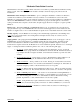
Using (figure 1) and visualizing the HeatChoice
installation, work through the following eight steps:
Step 1
Observe and select the insert location in the furnace
plenum.
a. Above A-coil
b. HeatChoice II hole cutout at A-coil end (facing
side)
c. Depending upon the specific model, between 8”
and 9.5” of space is required above the top of
the A-coil. This space is where the HeatChoice
II is physically inserted into the plenum.
d. 10” minimum (in addition to the space required
above) between control box and plenum top
e. All distribution ducts above A-coil top
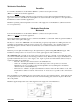
Step 2
Measure plenum width and depth
a. Step 1 determines facing side (hole cut decision)
b. Width
17” or less – 15” model
19” or less – 18” model
20” or greater – 18” model with baffling
(see below)
c. Depth
20” or less – no baffling
20” or greater – need rear baffling (see
below)
If your application falls in the 21” or greater mentioned above, field fabricate inside plenum baffling as shown
in (figure 2). (Reference EH101 at the back of this guide for more illustrations).
Figure 1
Figure 2