
Install Manual

04/03/2009 7 EI204
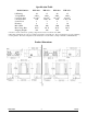
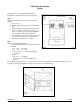
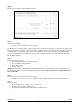
Step 3
Cut insert hole using provided template, (figure 3).
Step 4
Add necessary baffling.
a. See Step 2 for determination and if required.
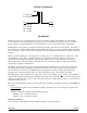
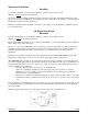
The HeatChoice is designed with a special double plate at the element mounting. Cool air from the blower must
blow between these two plates. Therefore, the Elector-Mate must be inserted into the base plenum such that the
mounting plate is even with the edge of the hot air outlet hole. Do not necessarily line up the Electro-Mate
control box with the furnace cabinet front. The concern is the hole in the bottom of the furnace mating with
Electro-Mate elements.
Step 5
Insert unit and bolt in place.
a. Extend center V deflector to plenum depth.
b. Do not drill into refrigerant lines.
c. Note airflow decal.
d. Seal as required.
NOTE: When handling or inserting the actual HeatChoice unit, verify the element or the element fins do not
become bent and the sensor probe is parallel with the top element. These probes must be approximately 1½”
from element fin.
Step 6
Be prepared to assist electrician with control wiring.
a. If utility load control is not used or required, verify the blue and blue/ white wire remains shorted.
Step 7
System checkout
a. Responsibility of the contractor who “sold the job”.
b. Warranty sheet suggests minimal steps.
c. Complete warranty sheet and send to Electro Industries, Inc.
Figure 3