
Install Manual

04/03/2009 14 EI204
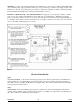
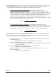
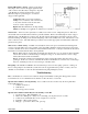
4. DECII module indicators (figure 11)
Front panel top red LED (Hi-limit) – illuminates
when high limit switch is open.
Front panel green LED (Control Power) – indicates
24-volt source from furnace and non-blown fuse.
Front panel red/green LED (Heat Source) –
indicates which heat source is being used, red =
gas, green = electric, flashing red/green = utility
load control.
Front panel bottom red LED (Heat Call) –
Indicates room thermostat call for heat.
Red LED (inside bottom) – gas furnace W is
receiving 24V.
5. Front panel heat source LED – this is a multifunction LED the chart below shows the various conditions
and functions of this LED.
Heat Source LED Status Condition
Solid green Normal operation, electric mode.
Solid red Normal operation, Stand-by mode.
Flashing red SOT timeout in electric mode, heating in stand-by.
Flashing green SOT timeout in stand-by mode, heating in electric
Flashing red/ green Utility load control heating in stand-by.
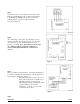
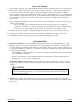
6. Stat Override Timer (SOT) – this is an internal timer which can be field set via the SOT jumper located on
the upper right hand side of the control board. If this set run time (90 or 180 minutes) is exceeded before
the thermostat is satisfied, the system automatically switches to either full electric elements or standby
depending upon the position of the stand-by/ electric switch. This option will automatically switch to
standby furnace if there is a system fault associated with inadvertent circuit breaker, manual reset hi-limit,
etc. If the HeatChoice unit is undersized (intentionally or unknown) this option will automatically switch to
standby heating if the HeatChoice electric unit cannot maintain temperature set point. Factory default is set
at 90 minutes, to disable the SOT function, remove the jumper. Note: the control board must be powered
down when making a change to the SOT jumper in order for the change to take affect.
NOTE: Utility Load Control has priority, in on-peak control there is no SOT.
7. High limit return – Independent of the XD jumper, the closing of the high limit will always perform a 2
minute delay for stages 2, 4, and 5.
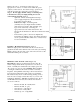
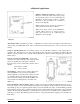
8. Secondary fan limit control – this sensor closes at 120°F on temperature rise. When closed, furnace G and
Y (BL) tabs are activated. Note: when installed using a variable speed furnace the closing of this probe will
only activate G or the continuous air function of the blower; it will force the blower to full speed.
9. Blower response – the blower has an approximate 10 second turn-on delay and will continue for 60 seconds
after electric element power is turned off via the room thermostat. This is necessary to properly cool off the
elements. Also note there is a 3 minute blower purge when switching from stand-by to electric.
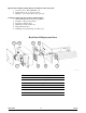
Figure 11