
Make Up Air II Spec Sheet

Installation Specifications (Reference Installation & Operating Instructions, EI916 or EI917)
Thisproductisdesignedforzeroclearance,butusethefollowingmountingandspacingcriteria:
1. Unitcanbeinstalledverticallyorhorizontally.Whenvertical,inletmustfacedown.
2. WhenusingCTdoughnut,useClassIIlowvoltagewiringmethodstoconnectCTtoMake-UpAirunit.
3. Makemountingprovisionsfora1”airspaceatthetop.
4. Thesides,anylocation,canbeindirectcontactwithwoodframingmaterials.
5. Nomaterialsshallbeincontactwiththecabinethousingwhichhasaamepointlessthanwood,300°F(150°C).
6. Productshallbeinstalledinaconditionedspaceonly.
7. Heatingelementsarelockedoutwhenenteringairtemperatureis>55°F(12.8°C).
ELECTRO INDUSTRIES, INC.
MONTICELLO, MN 55362
11
3
4
"
39
13
16
"
31
1
8
"
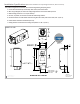
MODEL EM-MC*-*
8"
MODEL EM-MD*-*
10"
MALE DUCT
MODEL EM-MC*-*
8"
MODEL EM-MD*-*
10"
A
MALE DUCT
AIR
FLOW
INLET
6
13
16
"
5
11
16
"
31
1
2
"
1.125 x
.875
DOUBLE KNOCKOUT
13
9
16
"
14
5
16
"
DETAIL A
MODELS EM-MC* & EM-MD*
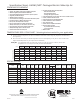
MODEL
DIM "A" DIM "B"
DIM "C" DIM "D"
DIM "E"
DIM "F"
DIM "G"
MB
12 5/8" 10 1/2" 29 3/8"
6
21"
20 5/8"
8 3/4"
MC
14 3/8" 13 1/2" 39 7/8"
8
31 1/2" 31 1/8" 11 3/4"
MD
14 3/8" 13 1/2" 39 7/8"
10
31 1/2" 31 1/8" 11 3/4"
ME,MF,MG
22 3/8" 19 1/2" 46 5/8"
14
38 1/4" 37 7/8" 17 3/4"
MAKE-UP AIR
ART-408
Rev.L 2/19/20
Sheet 3 of 4