
Make Up Air II Installation Manual

05/21/2019 23 EI914
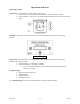
Start Up Inspection & Observations
Entering Air Temperature: Heating is locked out when entering air temperature is greater than 55°F
(12.7°C).
Blower Delay/Control – At the end of a cycle, the blower continues to run for approximately 30 seconds
to cool off the electric elements.
Depending upon inlet temperature, outlet temperature set point, and/or larger kW unit size; a power
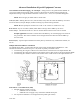
outage while the unit is in operation could cause the manual reset temperature limit control to open. The
reset button is located inside the control section of the cabinet.
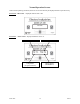
HI-LIMIT Functionality and Operation
Level One:
WarmFlo temperature control regulates the output temperature based on system setup
(see Basic Setup & Configuration). See Operational Indicators section (Red LEDs)
for more information on monitoring this sequence.
Level Two:
Software detection of high temperature. During an active cycle, the software will
check for a value > 100°F (38°C). If a temperature > 100°F (38°C) is detected, all
electric heating elements are disabled until the supply temperature reading drops < 90°F
(32°C). The most common cause for this hi-limit is low airflow (example, dirty filter).
See Operational Indicators section (Status LED) for more information on monitoring
this sequence.
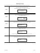
Level Three:
Automatic hi-limit/power relays. This is a mechanical component in the air stream
adjacent to the fan which opens a low voltage circuit to the control module upon
temperatures > 99°F (38°C) and resets upon temperatures < 85°F (29°C). Upon the
detection of this circuit being open, the control module disables the electric heating
element stages. Once this automatic hi-limit resets, the control module will then re-
enable the electric heating element stages. The most common cause for this hi-limit is
low airflow. See Operational Indicators section of this manual (Status LED) for more
information on monitoring this sequence.
Level Four: Automatic hi-limit. This is a mechanical component in series with the high voltage
(240V, L2 leg) to the electric heating elements and is located inside the element
chamber, top/sides. This automatic hi-limit will open at 100°F (38°C) and reset at 85°F
(29°C). The most common cause for this hi-limit is low airflow. Typically these limits
are detected monitoring current on the red wire with the use of a clamp-on amp meter.
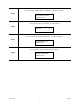
Level Five:
Manual hi-limit/software detection. This is a mechanical component which opens a
low voltage circuit to the control module upon temperatures > 150°F (65°C). Upon the
detection of this circuit being open, the control module disables the electric heating
element stages. The electric heating element stages will remain disabled until the user
manually resets the limit. The manual reset limit button is located in the control box
compartment. The most common cause for this hi-limit is no blower with electric
elements due to blower failure or mechanical failure of element relays. See Operational
Indicators section of this manual (Status LED) for more information on monitoring this
sequence.