
Make Up Air II Installation Manual

05/21/2019 24 EI914
Advanced Installation & Special Equipment Concerns
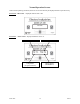
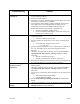
Override Electric Element Staging, “E” Tab Input – during an active call, spade terminal labeled “E”
(T7) can be jumpered to R (24VAC HOT) to bring on all four electric element stages and bypass any
temperature sensing or stage modulation functions. However, the > 55°F (12.7°C) disable still applies.
NOTE: Does not apply to models with no electric heat.
G IN (T3) Tab – Shorting this tab to “R” (24VAC HOT) at any time will cause this Make-Up Air unit to
turn on its blower (and open damper) without activating any electric heating elements.
NOTE: Blower speed upon connection of “G IN” to “R” will be low CFM blower only.
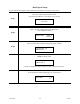
R IN NO NC –dry set of contacts (SPDT) which follows the logic of this Make-Up Air unit’s
blower/damper. The intention of this is to drive an external blower whenever this unit is activated.
Example application would be a scenario where the Make-Up Air is discharging in the return air
of a gas furnace: this contact would be used to energize the furnace blower when the Make-Up
Air is activated.
FAN ON (T5) – Special output intended to be used by factory technician only. Terminal has 24VDC, do
not use.
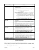
Multiple Exhaust Fan/Blower Installation
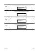
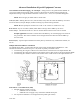
CT terminal block (TB2) – located on the left side of the control module labeled “HI MED LO”. This
terminal block allows connection of up to 3 CTs, based on quantity of exhaust sources.
CT monitoring the “largest” exhaust source blower motor would connect to the inputs labeled “HI”
CT monitoring the “mid-sized” exhaust source blower motor would connect to the inputs labeled “MED”
CT monitoring the “smallest” exhaust source blower motor would connect to the inputs labeled “LO”
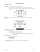
Information: CT terminal block (TB2)
Included with this product is one CT.
o Additional CTs are available.
o Additional CTs can apply to any of the three terminal block pairs.
Use only Electro Industries’ CTs designed for this product (part #3629).