
Make Up Air II Installation Manual

05/21/2019 25 EI914
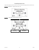
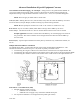
External Damper, Field Furnished and Installed:
Preparation or Pre-Wiring Sequence
1. Power up the Make-Up Air unit.
2. Jumper “R” and “W” screw terminal block (control board upper right).
3. Fan/blower will turn on and the internal damper will open. Observe the opening of the internal
damper.
4. With the internal damper open, disconnect all three wires. Separate, do not allow the gray wire to
touch either brown or violet wires.
5. Turn off the unit power and remove jumper at “R” and “W” terminal block.
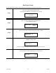
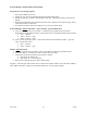
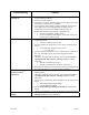
External Damper without End Switch – Select Actuator Type and Field Wires
A. 3-wire, power open/power close, 24VAC – extend the gray/violet/brown wires from the
disconnected internal damper actuator. Connect these wires to the field installed external actuator.
Gray – common
Violet – 24VAC = open
Brown – 24VAC = close
B. 2-wire, power open/spring return – extend wires from the internal damper actuator – gray and
violet. Cap off brown wire.
Gray – common
Violet – 24VAC = open
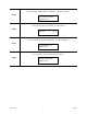
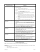
Damper with End Switch
1. Depending upon the type of actuator, select A or B above and field wire as detailed above.
2. Locate the “SB IN” or “END” tab, inside control board, lower right.
3. Connect the end switch (normally open) contacts as follows:
a. End Switch “SB IN” tab
b. End Switch “C” tab (common)
4. Pull or remove J24 peg jumper (to left of “SB IN” tab).
Sequence – with J24 open, there will be no fan or heat action until the “SB IN” tab is shorted to common.
With “SB IN” shorted to common, normal Electro Make-Up Air unit sequence begins.