
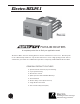
WarmFlo Electric Plenum Duct Heater Technical Data Manual
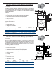
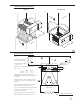

Upflow Downflow
&52.!#%
!)2
&,/7
!#/),
%,%#42/-!4%
7)$4(
3%%,!34$)')4
6
!)2
&,/7
%,%#42/-!4%
7)$4(
3%%,!34$)')4
&52.!#%
%8
2EV!
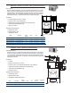
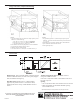
Plenum Heater Installation
Basic Mechanical, Upflow
OFFSET TAKEOFF CAN BE
3" BELOW EM TOP CUTOUT
ELECTRO-MATE
10" MINIMUM FROM
TOP OF EM CUTOUT
Duct
Dist.
Duct
Dist.
CORNER MUST BE
EM TOP CUTOUT
A-Coil
Upflow Only
1
5
4
2
6
3
7
8
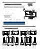
15-17.5"
18-19"
WIDTH
AMPS x VOLTS x 3.414
CFM =
1.08 x TEMP. DIFF.
17.5-19"
17.5-19"
DEPTH
15" MODEL
18" MODEL
4. Without A-coil, install Electro-Mate as high as
possible but maintain side takeoff position related to
the elements.
5. The Electro-Mate "V" must be installed parallel to
"A" frame of the coil and as close as possible to the
A-coil top.
6. Any plenum larger than 19” width or 20” depth
requires deflectors, see figures C-1 and C-2.
7. Shown is 20 kW model. 10 & 15 kW models have the
element stack 1.5" lower, thus the 3" can be
considered 1" min (25 kW, 5").
8. WarmFlo supply sensor (ST) is installed 12" above
Electro-Mate enclosure, directly above elements.
Notes:
1. If horizontal distribution is
not equal, increase to 14".
2. Electro-Mate hole opening -
8" x 15" or 8" x 18".
3. Plenum size - if larger baffling required, see
figure C-1 or C-2.
3" MIN.
EA107
rev.G 11-20-08