
WarmFlo EMB-H Installation and Operation Manual


05/19/2016 8 BI308
OPERATIONAL TIPS
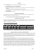
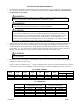
1. Indicator lights – there is a set of four indicator lights on the front cover. Figure 1 is a reproduction of the
front decal giving definition and information for using these indicator lights.
2. Boiler power LED indicates 24-volt is present on the control board and is continuous on. Off could mean
no 240 power, open manual reset (vessel top), open fuse, or bad transformer. It also indicates supply sensor
condition (solid = good, pulse = faulty).
3. 240-volt element power current flow can only be measured when the external operating thermostat is calling
for heat. There is a 30-second delay before stage 1 turns on, this allows the pump to circulate and sample
temperature. Stage 2 will depend upon the temperature differential at the sensor in the supply pipe, see page
9 sequence (assumes off-peak mode).
4. The operating thermostat heat call can be verified by the red LED marked “Mini-Boiler Heat ON” located
on front cover.
5. Utility off-peak LED is on when the boiler is not being load controlled (blue wires closed).
6. The hi-limit auto reset LED is on when the vessel top hi-limit switch is open.
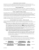
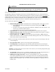
7. Via a small pin jumper arrangement on the control board, the circulator pump can
be a direct function of the “W” input or interrupted by the load control device (even
though there is a W input). This diagram illustrates this pin jumper arrangement.
This unit is factory setup in the “W” position meaning the pump will always run as
a direct function of “R” to “W” operating thermostat. By simply moving this black
2-position jumper to the “L” the pump will be turned off during load control
interrupt.
8. At outlet temperatures of approximately 160 F (53° C), the maximum operating system pressure should be
approximately 18 PSI (124 kPa). If the PSI (or kPa) increase from cold water to operating hot water is more
than approximately 3 to 4 PSI increase (20.6 to 27.5 kPa), the expansion tank is too small, or there is air in
the system.
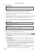
9. At the top of the vessel is a manual reset, 205° F (96° C), primary hi-limit. This is behind the upper control
board cover, at the top of the vessel. At the end of the two red/blk wires there is a small red stem between
the wire tabs. This is the reset button.
10. Check for water leaks and repair as required.
11. If flow seems to be a concern, determine both inlet and outlet water temperature and apply GPM (L/min)
formula detailed in previous section “Information/Water Flow Calculations”.
AQUASTAT OPERATION
Determine the design or anticipated outlet temperature. If this is a radiant floor system this typically could be
as low as 110°. If it is staple-up or water coil, satisfactory operation may be at 140° to 160°. If this is
baseboard or radiators, start with 170° and during very cold weather this may need to be 180°.
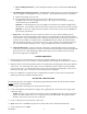
The front temperature set point is selected by a small screwdriver dial switch. Use the following chart:
Switch Position Set Point
0 90
1 102
2 114
3 126
4 138
5 144
6 160
7 180