ELECTRO-BOILER EZB-Eco® INSTALLATION & OPERATING INSTRUCTIONS Model: EZB-T1-05-240-1 EZB-T1-07-240-1 EZB-T1-10-240-1 EZB-T1-12-240-1 EZB-T1-15-240-1 EZB-T1-17-240-1 EZB-T1-20-240-1 APPLICATION: The EZB-Eco is a packaged system complete with boiler vessel, expansion tank, air eliminator and circulating pump. It is designed to be used in a variety of radiant hydronic heating applications. These include radiant floor, baseboard or radiator heating. These applications can be single or multiple zones.
TABLE OF CONTENTS Description Page Introduction 1 System or Water Flow 1 Multiple Zones & Radiant Temperatures 2 Zone Valves/Circulators 2 Room Thermostat Placement 2 Two-Temperature Operation or Feature 3 Boiler/Piping Placement 3 Installation Requirements 4 Clearances 5 Mechanical Installation – Under-Floor Radiation 6 Electrical Hookup 8 Water Fill Procedure 9 Controller Setup 10 Staging/Modulating Jumper 11 Operational Tips 11 Standby Switchover, SOT Timer 12 Replacemen
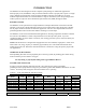
INTRODUCTION The EZB-Eco has been designed to be the complete system package for radiant heat applications. When properly sized, the EZB-Eco will provide the needed hot water to properly heat a space in a single zone or multiple zone application. With its unique WarmFlo technology, the EZB-Eco can easily modulate output based on the level of demand from a single or multi-zone system. Proper design of the radiant system is required to assure minimum required water flow (GPM) through the boiler.
MULTIPLE ZONES AND RADIANT TEMPERATURES Same water temperature all zones – in this case the system can be setup as one pump with the water circulated through the boiler and directly to a manifold containing the various zone valves. Although this model series has a built-in outlet sensing and controller mechanism for staging the elements, also consider the next section, Zone Controller.
bulb can later be pushed down this PVC conduit. If the slab is already poured without conduit for slab stat, use electronic remote sensing thermostat. B. Floor covering, medium to high insulation – use slab stat as described in paragraph A above. C. Quick response, hydronic tubing just under the concrete surface, no flooring material over the concrete – in this case, heated water can directly radiate into the room, a standard wall mount room thermostat is adequate.
INSTALLATION REQUIREMENTS 1. All installation work should be performed by trained, qualified contractors or technicians. Anyone installing this boiler should carefully study this manual prior to installation to get familiar with and plan how the boiler will be installed. WARNING ALL ELECTRICAL WIRING MUST BE IN ACCORDANCE WITH NATIONAL ELECTRIC CODE AND LOCAL ELECTRIC CODES, ORDINANCES, AND REGULATIONS. WARNING OBSERVE ELECTRIC POLARITY AND WIRING COLORS.
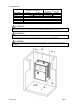
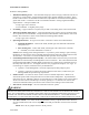
CLEARANCES SUGGESTED MINIMUM SERVICE CLEARANCE 1 INCH 26 MM 12 INCHES 305 MM 1 INCH 26 MM 12 INCHES 305 MM REQUIRED CLEARANCE – 0 INCHES/0 MM REQUIRED CLEARANCE – 6 INCHES/153 MM REQUIRED CLEARANCE – 14 INCHES/356 MM REQUIRED CLEARANCE – 14 INCHES/356 MM MINIMUM CLEARANCE LEFT SIDE RIGHT SIDE BACK FRONT TOP BOTTOM SURROUNDING AMBIENT TEMPERATURE MUST NOT EXCEED 90° F/32° C.
MECHANICAL INSTALLATION – UNDER-FLOOR RADIATION CAUTION Electro Industries Inc. requires the use of dielectric isolation between the boiler supply and return piping when the boiler is plumbed using copper or any other dissimilar metal. Damage to the vessel caused by galvanic corrosion voids Electro Industries’ warranty. Reference drawing BX603 1. Unpack the EZB-Eco boiler. Shipped loose from the boiler are outdoor sensor, pump check valve and mounting assist bracket. 2.
5. Piping between the EZB-Eco and hydronic system manifolds is shown on drawing BX603. When following this diagram, the water fill procedure becomes very simple and almost guarantees the removal of all air or prevents air locking problems. Experienced hydronic heating installers may be able to eliminate some components but the inclusion of these components guarantees installation and initial operating success.
ELECTRICAL HOOKUP Reference drawing BH601 1. 240/208-Volt Heating Power – route and install the proper current carrying conductors from service panel fuse or circuit breaker. See Specification Table and/or product nameplate for ratings. These models contain built-in circuit breakers and meet the requirement for local disconnect for appliances greater than 10 kW. Connection is at the circuit breaker terminals. If using single feed method, single feed bus – order part number 5701.
9. Flow Switch– a flow switch is not included or factory required for the boiler. However, one can be added to the LMC circuit. Simply place the field provided flow switch in series with this circuit. NOTE: The L/W (J3) jumper must be in the W position. WATER ADDITIVES/TREATMENT Water treatment is strongly suggested to prevent scale deposits, corrosion from acids, oxygen, and other harmful elements within the specific water supply.
CONTROLLER SETUP Front Dial Non-Outdoor Reset – simply set the knob to the desired outlet temperature on the front panel decal. This control strategy is accomplished via disconnecting the outdoor sensor and performing a power reset to the boiler (low voltage power cycle). Outdoor Reset – the temperature decal will relate to the OT 0° F set point and the knob numbers coincide with the curves below. High and low mass also relate to the ramp-up water temperature starting point, as shown.
Staging/Modulating Jumper The control board on the EZB-Eco boiler is a universal controller with the capability of interfacing with many different models of TS Electro-Boilers. The correct setting of this jumper is determined on the model of the boiler you are working with. For the EZB-Eco this should be set to MODULATE. Circulator pump mode – as factory set, the circulator pump is controlled directly from the W input terminal.
Manual Reset Hi-Limit At the top of the vessel there will be either two or three surface mount hi-limits preset at 205° F. There is no light indicator associated with these safety hi-limits. Also these 205° F safety limits break the L2 current carrying 240/208-volt wire going to the elements. Reset involves locating a small shiny lever or metal tab protruding on the side of the black safety limit base. This small tab is pressed inward approximately 1/8” to snap in the contacts.
Replacement Parts WFS2 WFS25F EB5623 UFUSE0443 4038KIT 5128C 5535 5537G 5453 5456 5652 5651 5650 5680 EB5526 EB5520 EB5524 5541 5585T 5590 5596 09/01/2020 Water sensor (ST), 5 ft. Outdoor sensor (OT), 25 ft.
TROUBLESHOOTING/REPAIR HELPS 1. This WarmFlo controller contains several interference suppression components, but as an electronic logic product, unpredictable and unusual transients or interference may sometimes cause strange results. If the WarmFlo controller is acting strange, one immediate step would be power down reset. Simply turn off boiler power or breaker number 1, when the green LED goes out, count to 1Ø, and re-energize power supply. 2.
OPERATIONAL INFORMATION Normal heating operation – when there is a heat call from the thermostat (24VAC present on the control board W-C terminals) the boiler pump will start and three indicator lights will illuminate on the front of the EZB-Eco: Boiler Power, steady green Electric Mode, steady yellow Thermostat Call, steady red After a short delay of one minute or less, the EZB-Eco will begin to stage up elements (as indicated by the four red staging LED’s on the inside control board) in order to rea
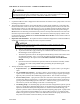
EZB MECHANICAL PIPING SCHEMATIC EZB BOILER IN OUT WATER SUPPLY BALL VALVE 1" X 1" X 3/4" TEE 1" PIPE NIPPLE 1" PIPE BALL VALVE 1" X 1" X 3/4" TEE DRAIN VALVE (THREADED INTO TEE) MANIFOLD Electro Industries, Inc. Monticello, MN 55362 (763)295-4138 BX603 REV.
UAW429 Rev.
EZB-**-** EZB SERIES HOOKUP, INSTALLATION 1 2 3 BH601 Rev.
UAW428 Rev.
BOILER ACCESSORIES ZONE CONTROLLER This will simplify your wiring and make zoning applications much easier. In addition, enhanced communicating features have the ability to stage the electric boiler based upon the connected zone capacity.
TWO SUPPLY WATER TEMPERATURE REQUIREMENT • • Handled as the priority zone on multi-zone (EB-ZEA-1) • • All other zones are held off Low Temp Priority switch on, zone 1 active - TS boiler automatically changes to 150° (or selection 176°) supply water setting With zone 1 satisfied or 60-minute timeout, the boiler automatically returns to the preset temperature and reacts to the other zones High Temp Radiant, slab Radiant, staple up Radiant, slab Baseboard Radiant, slab Fan coil Radiant, slab Wa
Electro Industries, Inc. Residential Limited Product Warranty Effective November 1, 2009 Electro Industries, Inc. warrants to the original owner, at the original installation site, for a period of two (2) years from date of original purchase, that the product and product parts manufactured by Electro Industries, Inc.
CONDITIONS AND LIMITATIONS: 1. This warranty is limited to residential, single family dwelling installations only. Any commercial or multi-unit dwelling installations fall under the Electro Industries Commercial Limited Product Warranty. 2. Electro Industries, Inc. shall not be liable for performance related issues resulting from improper installation, improper sizing, improper duct or distribution system, or any other installation deficiencies. 3.