
EZB-Eco Installation Manual


09/01/2020 8 BI601
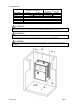
ELECTRICAL HOOKUP
Reference drawing BH601
1. 240/208-Volt Heating Power – route and install the proper current carrying conductors from service
panel fuse or circuit breaker. See Specification Table and/or product nameplate for ratings. These
models contain built-in circuit breakers and meet the requirement for local disconnect for appliances
greater than 10 kW. Connection is at the circuit breaker terminals. If using single feed method,
single feed bus – order part number 5701.
Only copper wire is allowed.
Circuit Breaker 1 is highest priority stage.
2. Grounding – copper conductor is required, size per NEC code relating to the current of each feed.
3. 120-Volt Circulating Pump Power – route and install the proper current carrying conductors from
service panel fuse or circuit breaker, 10-amp maximum. These models contain a built-in 10A circuit
breaker. Wire connection is at the circuit breaker and neutral/ground terminals.
Only copper wire is allowed.
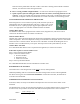
4. Operating Thermostat – two types can be used. Connection is at the control board bottom.
Standard Mechanical – connect to R and W, bottom right. Set thermostat internal heat
anticipator to 0.2.
Floor Sensing Stat – connect to R and W, bottom right. Place slab sensor in the slab.
If needed, can connect thermostat C to boiler C.
NOTE: Power robbing/power stealing thermostat – if you have a power robbing or power stealing
thermostat, you must use the resistor included with the thermostat. Place this jumper between boiler
W and boiler C. If resistor is not used, intermittent boiler operation can be expected.
5. Load Management Interrupt Control (LMC) – this Electro-Boiler series has been pre-wired and
designed for an external utility load management receiver connection. The control board lower left
terminal block marked BLU and BLU/WHT represent the two contact points, extend these wires to
the utility load control device. As shipped, this unit is only equipped for off-peak = N.C. logic. If
reversed logic is required, contact the factory for modification.
Optional – if load management is not used, simply keep the blue jumper in place.
Optional – if the power company disconnects 240V for load control, contact factory for
drawing BH029 for special wiring requirements.
6. Outdoor Sensor – the loose OT sensor needs to sense true outdoor temperature. Mount on an
outside wall position that will represent the most accurate outdoor temperature. If possible shade
from direct sun rays. Maintain a distance of 3 feet from dryer or other exhaust vents. Sensor length is
25 feet. The sensor can be extended up to 50 feet by splicing on a 3 conductor wire. Secure wire
connections should be made to prevent inaccurate or false sensor readings to the control board.
7. Zone Valves or Zone Pumps – see Zone Controller section for options.
WARNING
THE END SWITCHES FROM THE ZONE VALVES MUST BE AN ISOLATED CONTACT WITH NO VOLTAGE
PRESENT ON THESE WIRES OR SCREW TERMINALS. THIS IS VERY IMPORTANT TO MAKE SURE THERE
ISN’T ANY INTERFERENCE OR FEEDBACK BETWEEN THE TRANSFORMER OPERATING THE ZONE VALVE
SYSTEM AND THE TRANSFORMER WITHIN THIS ELECTRO-BOILER PRODUCT. ONCE THIS HAS BEEN
DETERMINED, ALL END SWITCHES ARE SIMPLY PARALLELED WITH THE TWO WIRES GOING TO R AND W.
8. Low Water Cutoff – a low water cutoff is not included or factory required for the boiler. However,
one can be added to the LMC circuit. Simply place the field provided flow switch in series with this
circuit.
NOTE: The L/W (J3) jumper must be in the W position.