
EZB-Eco Installation Manual


09/01/2020 3 BI601
bulb can later be pushed down this PVC conduit. If the slab is already poured without conduit for
slab stat, use electronic remote sensing thermostat.
B. Floor covering, medium to high insulation – use slab stat as described in paragraph A above.
C. Quick response, hydronic tubing just under the concrete surface, no flooring material over the
concrete – in this case, heated water can directly radiate into the room, a standard wall mount room
thermostat is adequate. Mount room thermostat on an inside wall similar to most heating systems.
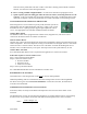
TWO-TEMPERATURE OPERATION OR FEATURE
When using Electro’s zone controller in priority mode, the boiler system can
automatically raise the outlet temperature with zone 1 calling. This is setup
for default of 150° F or pulling a jumper peg the high temperature value is
176° F. See appropriate zone controller installation manual for details.
Outdoor Reset Option
The EZB-Eco boiler comes equipped with an outdoor sensor (shipped loose). This sensor can be
connected to the board to allow for outdoor reset function.
What is Outdoor Reset?
Outdoor reset is where the Electro Boiler DT (desired water temperature) shifts up and down based on the
outdoor temperature. The water temperature coming out of the boiler will be higher when it’s cold outside
and lower when it’s warmer outside. The idea is to have the boiler work with the building heat loss to
maintain a more even BTU delivery to the space. This helps with overall system efficiency as well.
Outdoor Reset Activation
If it is determined that outdoor reset is required for this application, it needs to be activated.
Follow this sequence to activate outdoor reset:
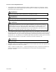
Step 1: Power down the Electro-Boiler
Step 2: Connect the outdoor sensor
Red wire to RED
Black wire to OT
White wire to COM
Step 3: Power up the Electro-Boiler
See: CONTROLLER SETUP for more information on outdoor reset.
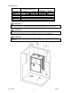
BOILER/PIPING PLACEMENT
This model series is wall hung and the vessel must be vertical, drawing BX603.
Additional plumbing items are located below the boiler housing itself as shown on drawing BX603.
For future servicing, the unit itself must be installed 18” or more above the floor, the elements are
screwed in from the bottom.
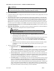
INFORMATION/WATER FLOW CALCULATIONS
Water flow, GPM, can easily be calculated if the temperature rise across the electric boiler can be
measured.
The formula below can only be used when the temperature rise is stable and the boiler is not hi-limiting.
In other words, verify constant current draw and stable outlet temperatures for at least 15 minutes.
GPM =
Volts x Amps x 3.4
500 x Temp. rise