
EZB-Eco Installation Manual


09/01/2020 6 BI601
MECHANICAL INSTALLATION – UNDER-FLOOR RADIATION
CAUTION
Electro Industries Inc. requires the use of dielectric isolation between the boiler supply and
return piping when the boiler is plumbed using copper or any other dissimilar metal. Damage
to the vessel caused by galvanic corrosion voids Electro Industries’ warranty.
Reference drawing BX603
1. Unpack the EZB-Eco boiler. Shipped loose from the boiler are outdoor sensor, pump check valve and
mounting assist bracket.
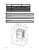
2. The mounting assist bracket is used to hold the boiler in place during installation. Locate where the
bottom of the boiler will be on the wall. Securely fasten the mounting assist bracket to the wall with
the bent flange sticking out. This will allow you to “rest” the boiler between the flange and the wall
while the boiler is secured to the wall installing mounting bolts through side and top boiler flanges.
Do not remove the mounting assist bracket until you have securely bolted the boiler to the wall. The
unit must be positioned with the vessel vertical. The unit will not function properly with the vessel
in a horizontal position. NOTE: Mount at least 18 inches above the floor to allow element removal
and service at the bottom.
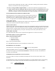
3. Expansion tank installation – the expansion tank is included but shipped loose within the EZB-Eco,
and must be installed prior to filling the boiler and system with fluid.
CAUTION
Use proper tools to install expansion tank. Attempting to tighten by hand will result
in damage to the expansion tank.
a. Remove and unpack the expansion tank from within the EZB-Eco enclosure.
b. To prevent water leaks, apply Teflon tape or suitable thread sealant (not included) to the
threaded nipple of the expansion tank.
c. Thread the expansion tank into the designated shutoff fitting located at the bottom of the
air eliminator assembly. Use a 7/8” wrench to tighten the expansion tank at the
designated fitting on the expansion tank. DO NOT ATTEMPT TO TIGHTEN BY
HAND.
d. Open the shutoff valve between the expansion tank and air eliminator assembly. Failure
to open the valve will create problems when pressurizing the system during fill
procedures.
4. The key mechanical components included with the EZB-Eco are:
Expansion Tank – provides constant system pressure. The expansion tank is pre-charged to
12psi.
Air Vent/Inline Air Separator – provides a means to trap and remove air from the hydronic
system. Loosen small cap on top of air eliminator to allow air to purge. Tighten cap to finger
tight only after system has been sufficiently purged of all air. This can take several days.
Pressure Safety Valve – 30psi pressure relief valve will release water when system pressure
exceeds 30psi. During purging there is a requirement to bleed out the initial air within this 1”
pipe leg by manually holding open the relief valve. Add the necessary pipe extension to the
relief valve to prevent water damage on this unit or surrounding area.
Circulating Pump – the included pump provides water flow throughout the hydronic system.
This is a 3-speed pump, shipped from the factory set to high speed. The pump speed may be
adjusted as needed for ideal system temperature rise. Electro recommends allowing your
hydronic system to warm to desired temperature before adjusting pump speed. A pump check
valve is shipped loose with the EZB-Eco. For single pump systems it is not required. If the
EZB-Eco is piped in conjunction with a fossil fuel boiler with internal pump, the check valve
may need to be installed. Contact the factory for more information.