EVID C12.
Table of Contents Table of Contents ............................................................................................................. TOC Safety First ....................................................................................................................... TOC Packing List ............................................................................................................................ 1 EVIDTM C12.2 Models .................................................................
Packing List Figure Quantity Part A 1 Speaker System B 1 Grille C 1 Owner's Manual D 1 Terminal Connector E 1 Warranty Card F 1 Ceiling Cutout Template G 1 Paint Shield H 2 Tile Rails I 1 C-Ring Support J 2 Support Ring Screws A D B F E C G I J (x2) H (x2) Figure 1: EVID C12.2 Packing List EVIDTM C12.
EVIDTM C12.2 Models Model Part No. Description 12" Coaxial Speaker System, Consists of CE-12 and EVID 920-8B Assembled, 64W Transformer with ASC* 12" Enclosure for EVID 920-8B, Includes 64W CE-12 301921-100 Transformer with ASC* High-Efficiency 12" Coaxial Driver, 100 dB EVID 901922-100 920-8B Sensitivity, 200W Power Handling C12.
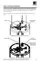
Open Ceiling Installation The EVID C12.2 must be suspended from the back of the can in both open ceiling and ceiling tile applications, using either the 3 pendant mount tabs or the 3/8” threaded rigging point. To prevent rattles, rotate the 4 mounting tabs towards the can, then tighten the mounting tab screws. The seismic tab may be used in addition to the pendant mounts as a redundant safety point.
Ceiling Tile Installation Step 1: Cut the Hole (Figure 5) Cut out the hole by tracing the cardboard template or with a circular cutter set to the appropriate cutout size. If the wire has been pre-installed, pull the wiring through the cutout hole. Figure 5: Cut Ceiling Hole Step 2: Install C-Ring and Tile Rails (Figure 6) For suspended ceiling installations, insert the C-ring through the hole cut in the ceiling tile. Place the C-ring around the hole with the tabs located as shown in Figure 6.
Installation Note: Tile Rails and C-Ring The tile rail accessory is designed to fit either standard 24-inch-wide or 600-mm-wide tiles. It is important to note that the tile rail pieces do not actually attach to the T-grid struts.The ends of the rails sit OVER the Tgrid strut. Normally, the tile supports the rails. The tile rails are prepunched at regular intervals with holes along their length.This allows the C-ring to be positioned at any point along the rail.
Installation Note: Connector Wiring Guidelines The input connector’s 4 terminals are numbered and marked on the connector. Pins 1 and 2 are positive (+); pins 3 and 4 are negative (–). (Pin 1 is connected to Pin 2 and Pin 3 is connected to Pin 4 inside the speaker.) Pins 1 and 4 are used as daisy-chain connections to other loudspeakers. For wiring in parallel, connect the wire pair of the subsequent speaker to pins 1 and 4. When one input connector is removed, subsequent speakers will also be disconnected.
Step 4: Secure the Cable to the Speaker (Figure 10) Fully loosen the horizontal screw shown in Figure 9, then the strain relief screws. Run the wires through the opening in the fitting and plug the input connector into the speaker’s terminal block. Then tighten the strain relief fitting as follows: If plenum cable is used, slide the cable through the strain relief fitting on the terminal cover plate (Figure 10). Hold the strain relief fittings tight around the cable.
Step 5: Mount the Speaker Into the Ceiling (Figure 11) Push the speaker into the ceiling hole until the front baffle rim is flush with the ceiling. Tighten the mounting tabs by turning the screw clockwise until the speaker is secure. Please note that the first clockwise quarter turn rotates the attachment tabs outward. The remaining turns tighten the tabs down onto the back of the ceiling surface (see Figure 12). Installation Note: See Page 3 for possible installation methods.
Step 7: Adjust Tap Selector (Figure 14) The tap selector switch is located on the front baffle. Adjust the speaker to the appropriate tap setting before installing the grille. In some 70V/100V constant voltage installations it is advisable to leave the grilles off if final speaker audio level balance adjustments are to be made later. After the levels are adjusted the grilles can then be installed.
Appendix A - Painting the Speaker If the speaker is installed in an area where the interior design requires a color match, the EVID C12.2 is simple to paint. The speaker can accommodate almost any type of latex or oil based paint. The bezel/rim can be painted before installation or after mounting into the ceiling. Paint Shield Painting Process Clean the rim and grille with mineral spirits or other light solvent. Do not use harsh solvents such as gasoline, kerosene, acetone, or other chemicals.
Appendix B - Troubleshooting Table Problem Possible Causes Action Make sure the amplifier channel is being fed an input signal (preferably via a "signal input" indicator on the amp). Check that the amplifier channel's volume is turned up. Amplifier Connect the speaker and cable, which had no output No Output to another amplifier channel, making sure an imput signal is fed to the new ampl channel. If you then get output, the problem was the amplifier channel.
Appendix C - Specifications Figure 18: Dimension Drawings Dimensions (Depth x Diameter): 333mm x 414mm (13.12" x 16.31") Cutout Diameter: Weight: 390mm (15.35") 13.3 kg (29.3 lbs) Cabinet Construction: Transducer: EVID 920-8B, 12 in.
Notes EVIDTM C12.
12000 Portland Avenue South Burnsville, MN 55337 Phone: 952/884-4051 Fax: 952/884-0043 www.electrovoice.com © Telex Communications, Inc. 12/2007 Part Number LIT000072 Rev C U.S.A. and Canada only. For customer orders, contact the Customer Service department at 800/392-3497 Fax: 800/955-6831 Europe, Africa and Middle East only.