
Owner`s manual


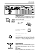


POWER AMPLIFIER INPUTS
“PHOENIX”-type connectors are provided parallel to the XLR-type
inputs, offering the opportunity to feed additional power amplifiers
with identical signals.
The inputs are electronically balanced with pin-assignment accor-
ding to the IEC 268 standard.
Pin-assignment of the XLR-type input connectors:
Pin-assignment of the “PHOENIX”-
type connectors:
Input sensitivity is factory set to 1Vrms.
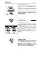
LEVEL CONTROLS
dB-scaled potentiometers for the adjustment of the power ampli-
fier’s overall amplification. These controls should be set between
0 dB and –6 dB, depending on the output of the connected signal
source device – e. g. a mixing console. The printed scale shows
the actual amount of damping in the amplification of the power
amplifier.
INPUT ROUTING
PARALLEL MONAURAL
Setting the selector switch to the PARALLEL/MONO position puts
the channel A and channel B inputs in electrically direct parallel
configuration, leaving you with the opportunity to individually con-
trol the channels’ level settings by the use of the output controls A
and B.
DUAL STEREO
When the selector switch is set to its DUAL/STEREO position both
channels are amplified separately.
PIN 1: SHIELD
PIN 2: a, +
PIN 3: b, -
REAR PANEL
11