OWNER‘S MANUAL BEDIENUNGSANLEITUNG MODE D‘EMPLOI
CONTENTS IMPORTANT SAFETY INSTRUCTIONS IMPORTANT SERVICE INSTRUCTIONS DESCRIPTION UNPACKING & WARRANTY INSTALLATION NOTES FRONT VIEW REAR VIEW INPUT A / INPUT B PARALLEL POWER AMP OUTPUT BRIDGED MODE GROUND-LIFT SWITCH MAINS INPUT SPECIFICATIONS / TECHNISCHE DATEN BLOCK DIAGRAM DIMENSIONS / ABMESSUNGEN ....................... ....................... ....................... ....................... ....................... ....................... ....................... ....................... ...............
IMPORTANT SAFETY INSTRUCTIONS The lightning flash with arrowhead symbol, within an equilateral triangle is intended to alert the user to the presence of uninsulated “dangerous voltage“ within the product’s enclosure that may be of sufficient magnitude to constitute a risk of electric shock to persons. The exclamation point within an equilateral triangle is intended to alert the user to the presence of important operating and maintenance (servicing) instructions in the literature accompanying the appliance.
DESCRIPTION Congratulations! With buying a Electro-Voice CP-SERIES power amplifier you have chosen an appliance that employs most advanced technology. CP-Series power amps combine outstanding audio performance, highest reliability and operational safety. The audio performance of CP power amps are simply extraordinary. Optimised power supply units employing low-leakage toroidal transformers and the consistent use of Class-H technology provide extensive headroom far above the stated nominal output.
DESCRIPTION UNPACKING & WARRANTY Carefully open t he packaging and take out the power amplifier. Next to the power amplifier itself, the package also includes this owner’s manual, a mains cord and the warranty certificate. Keep the original invoice, which states the purchase/delivery date together with the warranty certificate at a safe place. INSTALLATION NOTES Generally, installing or mounting power amps should be carried out in a way that guarantees continuously unopposed front-to-rear air circulation.
FRONT PANEL Use the POWER switch, located on the front panel’s, right side to switch the appliance’s power on. The soft-start function limits against current inrush peaks on the mains, which in addition prevents the mains line protection switch from activating during power-on. The loudspeaker outputs are activated via relay switching with a delay of approximately 2 seconds to efficiently attenuate eventual power-on noise. The PROTECT LED lights during the delay time and the fans run at maximum speed.
REAR PANEL The inputs INPUT A & INPUT B of the CP series are electronically balanced. The voltage gain of all models is set to 32 dB (constant gain). This results however in different input sensitivities for the different models (see table), but the level adjustment of active crossovers or signal processors in multi-way systems is much easier.
REAR PANEL POWER AMP OUTPUT CONNECTORS Power amp output connection for the two channels A (left) and B (right) is provided via SPEAKON-type output connectors. A plastic cover to prevent inadvertent erroneous connection protects the BRIDGED OUT connector. Make sure to remove the cover only when actually operating the power amplifier in Bridged-Mode.
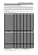
MAINS OPERATION & RESULTING MAINS OPERATION & RESULTING TEMPERATURE The following tables allow determining power supply and cabling requirements. The power drawn from the mains network is converted into output power to feed the connected loudspeaker systems and into heat. The difference between power consumption and dispensed power is called power dissipation (Pd). The amount of heat resulting from power dissipation might remain inside of a rack-shelf and needs to be diverted using appropriate measures.
MAINS OPERATION & RESULTING CP2200 idle Max. Output Power @ 8Ω (1) Max. Output Power @ 4Ω (1) Pmains [W] Pd (6) [W] BTU/hr(4) Umains [V] Imains [A] 230V 0,5 65 - 65 220 230V 8,0 1440 2 x 500 440 1500 Pout [W] 230V 13,2 2520 2 x 800 920 3140 1/3 Max. Output Power @ 4Ω (1) 230V 7,5 1360 2 x 266 828 2825 1/8 Max. Output Power @ 4Ω (1) 230V 3,0 520 2 x 100 320 1090 1/8 Max.
BEDIENUNGSANLEITUNG
INHALT WICHTIGE SICHERHEITSHINWEISE WICHTIGE SERVICEHINWEISE BESCHREIBUNG AUSPACKEN & GARANTIE INSTALLATIONSHINWEISE FRONTSEITE RÜCKSEITE INPUT A / INPUT B PARALLEL ENDSTUFENAUSGÄNGE BRIDGED MODE GROUND-LIFT SCHALTER NETZEINGANG NETZBETRIEB & WÄRMEENTWICKLUNG SPECIFICATIONS / TECHNISCHE DATEN BLOCK DIAGRAM DIMENSIONS / ABMESSUNGEN 12 ....................... ....................... ....................... ....................... ....................... ....................... ....................... ......
WICHTIGE SICHERHEITSHINWEISE Das Blitzsymbol innerhalb eines gleichseitigen Dreiecks soll den Anwender auf nicht isolierte Leitungen und Kontakte im Geräteinneren hinweisen, an denen hohe Spannungen anliegen, die im Fall einer Berührung zu lebensgefährlichen Stromschlägen führen können. Das Ausrufezeichen innerhalb eines gleichseitigen Dreiecks soll den Anwender auf wichtige Bedienungssowie Servicehinweise in der zum Gerät gehörenden Literatur aufmerksam machen. 1. 2. 3. 4. 5. 6. 7.
BESCHREIBUNG Herzlichen Glückwunsch! Sie haben sich mit einer Endstufe der CP-SERIE von Electro-Voice für ein Gerät modernster Technologie entschieden. Die Endstufen der CP-Serie vereinen überragendeAudio-Performance mit höchster Zuverlässigkeit und Betriebssicherheit. Die Übertragungseigenschaften der CP-Endstufen sind hervorragend.
BESCHREIBUNG AUSPACKEN & GARANTIE Öffnen Sie die Verpackung und entnehmen Sie die Endstufe. Zusätzlich zu dieser Bedienungsanleitung liegen dem Gerät ein Netzkabel, und die Garantiekarte bei. Bewahren Sie zur Garantiekarte auch den Kaufbeleg, der den Termin der Übergabe festlegt, auf. INSTALLATIONSHINWEISE Generell sind die Endstufen so aufzustellen oder zu montieren, dass die Luftzufuhr an der Frontseite und die Entlüftung an der Geräterückseite nicht behindert wird.
FRONTSEITE Mit dem POWER Schalter rechts auf der Frontblende wird das Gerät eingeschaltet. Eine SoftstartSchaltung vermeidet dabei Einschaltstromspitzen auf der Netzleitung. Dadurch wird verhindert, dass der Leitungsschutzschalter des Stromnetzes beim Einschalten der Endstufe anspricht. Die Lautsprecher werden über die Ausgangsrelais um ca. 2 Sekunden verzögert zugeschaltet, wodurch etwaige Einschaltgeräusche effektiv unterdrückt werden, die ansonsten in den Lautsprechern hörbar wären.
RÜCKSEITE Die Eingänge INPUT A und INPUT B der CP-Serie sind elektronisch symmetrisch ausgeführt. Die Spannungsverstärkung aller Modelle ist auf 32dB (Constant Gain) eingestellt. Damit ergeben sich zwar unterschiedliche Eingangsempfindlichkeiten für die verschiedenen Modelle (siehe Tabelle), aber die Pegeljustierung von elektronischen Frequenzweichen bzw. Signalprozessoren im Mehrwegsystemen wird dadurch wesentlich vereinfacht.
RÜCKSEITE ENDSTUFENAUSGANGSBUCHSEN Für die Endstufenkanäle A (Links) und B (Rechts) sind jeweils SPEAKON Ausgangsbuchsen vorhanden. Die BRIDGED OUT Buchse für den Brückenbetrieb ist mit einem Kunststoffdeckel geschlossen, um Anschlussfehler zu vermeiden. Entfernen Sie den Deckel nur, wenn Sie die Endstufe tatsächlich im Brückenbetrieb verwenden wollen. ACHTUNG! Zum bequemen Anschluss von 2-Weg Lautsprechern (z.
NETZBETRIEB & WÄRMEENTWICKLUNG NETZBETRIEB & WÄRMEENTWICKLUNG IN DER ENDSTUFE Mit Hilfe der folgenden Tabellen können die Anforderungen für Stromversorgung und Zuleitungen bestimmt werden. Die vom Stromnetz aufgenommene Leistung wird in Ausgangsleistung für die Lautsprecher und in Wärme umgewandelt. Die Differenz aus aufgenommener Leistung und abgegebener Leistung nennt man Verlustleistung (Pd). Die durch Verluste entstehende Wärme verbleibt u.U.
NETZBETRIEB & WÄRMEENTWICKLUNG CP2200 idle Umains [V] Imains [A] Pmains [W] Pout [W] Pd (6) [W] BTU/hr(4) 230V 0,5 65 - 65 220 Max. Output Power @ 8Ω (1) 230V 8,0 1440 2 x 500 440 1500 Max. Output Power @ 4Ω (1) 230V 13,2 2520 2 x 800 920 3140 1/3 Max. Output Power @ 4Ω (1) 230V 7,5 1360 2 x 266 828 2825 1/8 Max. Output Power @ 4Ω (1) 230V 3,0 520 2 x 100 320 1090 1/8 Max.
MODE D‘EMPLOI
MATIÈRES IMPORTANTES INFORMATIONS DE SÉCURITÉ INSTRUCTIONS DE RÉPARATION IMPORTANTES DESCRIPTION DÉBALLAGE ET GARANTIE REMARQUES SUR L’INSTALLATION FACE AVANT PANNEAU ARRIÈRE INPUT A / INPUT B PARALLEL SORTIE DE AMPLI DE PUISSANCE GROUND-LIFT ENTRÉE SECTEUR SECTEUR ET TEMPÉRATURE RÉSULTANTE SPECIFICATIONS BLOCK DIAGRAM DIMENSIONS 22 ....................... ....................... ....................... ....................... ....................... ....................... ....................... .......
INSTRUCTIONS DE SÉCURITÉ IMPORTANTES Le symbole représentant un éclair fléché dans un triangle équilatéral a pour but d’alerter l’utilisateur de la présence d’une „tension dangereuse“ non isolée à l’intérieur du boîtier, pouvant être d’une force suffisante pour constituer un risque d’électrocution.
DESCRIPTION Félicitations ! En achetant un amplificateur de puissance Electro-Voice CP-SERIES, vous avez choisi un appareil qui emploie les technologies les plus modernes. Les performances audio des amplis de puissance CP sont tout simplement extraordinaires.
DESCRIPTION DÉBALLAGE ET GARANTIE Ouvrez avec précautions le carton d’emballage et sortez votre amplificateur de puissance. En plus de l’amplificateur de puissance lui-même, le carton contient également le présent mode d’emploi, le cordon secteur et le certificat de garantie. Conservez en lieu sûr, l’original de la facture, qui mentionne la date d’achat et de livraison, ainsi que le certificat de garantie.
FACE AVANT Utilisez l’interrupteur secteur, situé en face avant, du côté droit, pour mettre l’appareil sous tension. La fonction Soft-Start élimine les crêtes provoquées par l’appel de courant à l’allumage, ce qui par la même évite que le commutateur de protection secteur ne s’enclenche lors de la mise sous tension. Les sorties haut-parleur sont activées via la commutation d’un relais avec une temporisation d’environ 2 secondes de façon à atténuer efficacement d’éventuels bruits de mise sous tension.
PANNEAU ARRIÈRE INPUT A / INPUT B Les entrées INPUT A & INPUT B de la série CP sont symétrisées électroniquement. Le gain de tension de tous les modèles est réglé sur 32 dB (gain constant). Toutefois il en résulte des sensibilités d‘entrée différentes selon les modèles (voir tableau), mais le réglage de niveau des filtres actifs ou des processeurs de signal dans les systèmes multi-voies est beaucoup plus simple.
PANNEAU ARRIÈRE CONNECTEURS DE SORTIE DE AMPLI DE PUISSANCE Les connecteurs de sortie de l’ampli de puissance pour les deux canaux A (gauche) et B (droit) sont des prises de type SPEAKON. Un cache en plastique protège le connecteur BRIDGED OUT de tout branchement erroné. N’enlevez ce cache que lorsque vous souhaitez réellement faire fonctionner l’amplificateur de puissance en mode Dérivation (Bridged).
ALIMENTATION SECTEUR ET TEMPÉRATURE RÉSULTANTE ALIMENTATION SECTEUR ET TEMPÉRATURE RÉSULTANTE Le tableau suivant indique les normes d’alimentation secteur et de câblage. Le courant d’alimentation secteur est converti en puissance de sortie pour alimenter les haut-parleurs connectés et en chaleur. La différence entre la consommation électrique et la puissance dispensée est appelée puissance dissipée (Pd).
ALIMENTATION SECTEUR ET TEMPÉRATURE RÉSULTANTE CP2200 idle Max. Output Power @ 8Ω (1) Max. Output Power @ 4Ω (1) Pmains [W] Pd (6) [W] BTU/hr(4) Umains [V] Imains [A] 230V 0,5 65 - 65 220 230V 8,0 1440 2 x 500 440 1500 Pout [W] 230V 13,2 2520 2 x 800 920 3140 1/3 Max. Output Power @ 4Ω (1) 230V 7,5 1360 2 x 266 828 2825 1/8 Max. Output Power @ 4Ω (1) 230V 3,0 520 2 x 100 320 1090 1/8 Max.
SPECIFICATIONS - Amplifier at rated conditions, both channels driven, 8Ω loads, unless otherwise specified. CP1200 CP1800 CP2200 2Ω 4Ω 8Ω 2Ω 4Ω 8Ω 2Ω 4Ω 8Ω 600W 400W 240W 900W 600W 350W 1100W 800W 500W --- 300W 150W --- 500W 250W --- 700W 350W Max. Single Channel Output Power Dynamic Headroom, IHF-A 1100W 580W 300W 1450W 850W 450W 2200W 1200W 625W Max.
BLOCK DIAGRAM 32
DIMENSIONS /ABMESSUNGEN 33
NOTES 34
NOTES
USA Telex Communications Inc., 12000 Portland Ave. South, Burnsville, MN 55337, Phone: +1 952-884-4051, FAX: +1 952-884-0043 Germany EVI AUDIO GmbH, Hirschberger Ring 45, D 94315, Straubing, Germany Phone: 49 9421-706 0, FAX: 49 9421-706 265 Subject to change without prior notice. www.electrovoice.