
Owner's Manual

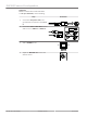

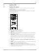

Table Of Contents

Amplifier DSP
Amplifier DSP controls
The amplifier has a combination of controls and connectors to ensure the most versatile
loudspeaker system.
Full-Range loudspeaker control and monitoring interface
The full-range loudspeaker DSP control menu selections are available for the ELX200-10P,
ELX200-12P, and ELX200-15P.
RL
QuickSmartDSP MONITOR|
AUX IN
OUTPUT
MASTER VOL
INPUT 1
INPUT 2
PUSH FOR D SP
ELX200
WARNING: ,TO REDUCE R ISK OF SHOCK DO NOT
.EXPOSE TH IS APPLIANCE TO RAI N OR MOISTURE
MAINS IN
CAUTION
RISK OF ELECTRIC SHOCK
DO NOT OPEN
RISQUE DE CHOC ELECTRIQUE NE
PAS OUVRIR
AVIS
1
2
3
4
8
7
5
6
Figure 5.1: Full-Range loudspeaker amplifier panel
1. LCD – DSP control and monitoring interface.
2. MASTER VOL – Adjusts the sound level.
DSP – Scroll through the menu and select the available choices. Push the MASTER VOL
knob to enter the DSP menu.
3. INPUT LEVEL – Level control for adjusting the individual inputs’ level. The 12 o’clock
position is unity gain (no gain or attenuation), the range to the left of zero (0) is for
adjusting line level sources, and the range to the right of zero (0) is for adjusting
microphone levels. LINE and MIC input level control is available for both INPUT 1 and
INPUT 2.
4. INPUT – Balanced input for the connection of signal sources like mixing consoles,
instruments, or microphones. Connections can be established using ¼ inch TRS or XLR
connectors.
5. POWER – AC switch for switching the power ON or OFF. The LCD screen lights up when
the power is turned ON, after approximately 3 seconds.
6. MAINS IN – AC connection is established via an IEC-connector.
7. OUTPUT – XLR output sends the mix of both input signals to another loudspeaker or
subwoofer. INPUT LEVEL controls the signal level to OUTPUT. The MASTER VOL or DSP
control settings do not affect OUTPUT.
5
5.1
en 19
Electro-Voice Installation manual 2017.06 | 01 | F.01U.326.891