
Specifications


Note the position of the HF shading switch card. The card must be replaced in exactly the
same position as it was originally or system performance will be adversely affected!
EVA components are wired in pairs. Therefore, both woofers will be tested together at the
same time, as will the upper HF compression driver pair and the lower HF compression driver
pair. Each HF compression driver pair has its own PTP network and these are also tested
separately. EVA DCR values are referenced to the black (common) test point (See Figure 6).
To directly access transducer pairs for more sophisticated testing, substitute the (-) input con-
nection on the input terminal block for the black (common) test point on the access card (See
Figure 9). Note: DCR values listed are not valid for this connection.
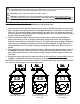
1. Test the woofers: Place one test lead securely on the RED test point and the other on the
BLACK (common) test point on the Access Card. A properly functioning woofer pair will
read approximately 43.2 ohms DCR, ±1 ohm (See Figure 6). A significantly higher reading
indicates one of the woofers has an open voice coil, meaning the woofer needs to be re-
placed. A significantly lower reading indicates one or both of the woofers has a voice coil
that is shorting, meaning the woofer(s) must be replaced.
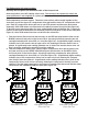
2. Test the compression driver pairs: Test the upper compression driver pair by placing one
test lead securely on the UPPER YELLOW test point and the other on the BLACK (com-
mon) test point on the Access Card. A properly functioning compression driver pair will
read approximately 41.6 ohms DCR, ±1 ohm (See Figure 7a). A significantly higher reading
indicates one of the compression drivers has an open voice coil, meaning the compres-
sion driver(s) must be replaced. A significantly lower reading indicates one or both of the
compression driver voice coils are shorting, meaning the compression driver(s) must be
replaced. Test the lower compression driver pair by repeating the above test with the meter
connected to the LOWER YELLOW test point (See Figure 7b).
Figure 6:
EVA Woofer Pair Test
Figure 7a:
EVA Upper Compression
Driver Pair Test
Figure 7b:
EVA Lower Compression
Driver Pair Test
43.2 41.6 41.6